Catalytic device and organic waste gas treatment system

A technology of organic waste gas and catalytic devices, applied in gas treatment, chemical instruments and methods, separation methods, etc., can solve problems such as explosions and VOC accidents, and achieve the effect of preventing explosion hazards and realizing self-cleaning

Inactive Publication Date: 2021-04-02
LIAONING TECHNICAL UNIVERSITY
View PDF16 Cites 1 Cited by
  • Summary
  • Abstract
  • Description
  • Claims
  • Application Information

AI Technical Summary

Problems solved by technology

However, because VOC has the characteristics of instantaneous changes in flow rate and concentration, accidents often occur in VOC processing
Once the high-concentration organic waste gas enters the treatment equipment, accidents such as explosions will occur instantly

Method used


Image

  • Catalytic device and organic waste gas treatment system

Examples


Embodiment 1

[0030] A catalytic device, characterized in that, comprising:

[0031] Reactor 1, inside the reactor 1, a filter 2 and an adsorption catalyst 3 are sequentially arranged along the flow direction of the organic waste gas;

[0032] The filter 2 is a wall-flow silicon carbide ceramic filter, and the load on the filter 2 includes: manganese oxide 1%-3%, cerium oxide 0.5%-1%, cobalt oxide 0.5%-1%, Palladium 0.3%-0.5% and platinum 0.3%-0.5%; with filtering and catalytic functions, it can filter out heavy oil, particles, and droplets in VOC exhaust gas. At the same time, it has a catalytic function at 300°C, which can catalyze and oxidize VOC waste gas into water and carbon dioxide.

[0033] The adsorption catalyst 3 includes the following components: 23%-25% of ZSM-5 molecular sieve, 25%-35% of beta zeolite molecular sieve, 10%-30% of activated alumina, 8%-12% of nanometer manganese oxide, zinc oxide 2 %-4%, iron oxide 3%-6%, palladium 0.3%-0.5% and platinum 0.3%-0.5%, with filter...

Embodiment 2

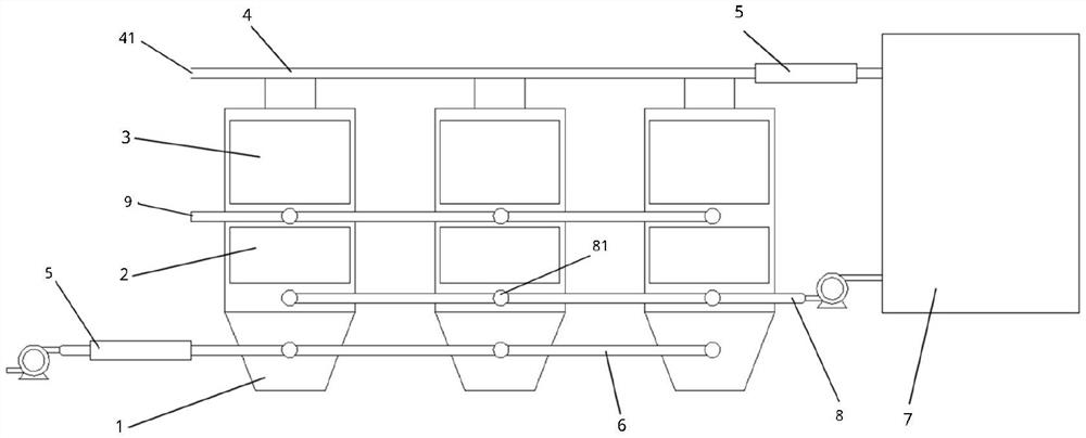
[0035] An organic waste gas treatment system, characterized in that it comprises:

[0036] The combustion chamber 7 is connected with an intake pipeline, and the intake pipeline is divided into two sections, the first pipeline 6 and the second pipeline 4; the combustion chamber is used for incinerating organic waste gas.

[0037] The catalytic device described in Embodiment 1 is arranged between the first pipeline 6 and the second pipeline 4;

[0038] The first pipeline 6 connects the intake end of the catalytic device and the exhaust gas source, the second pipeline 4 is connected between the gas outlet end of the catalytic device and the combustion chamber 7, and the second pipe A combustion-supporting air inlet 41 is also provided on the road 4 . The organic waste gas whose concentration has been reduced by catalysis is mixed with the combustion-supporting air and then blown into the combustion chamber.

Embodiment 3

[0040] On the basis of embodiment 2, increase:

[0041] A flame arrester 5, the first pipeline 6 and the second pipeline 4 are both provided with a flame arrester 5 . Further preferably, the flame arrester is formed by extruding silicon carbide, and the flame arrester is honeycomb-shaped and has a ceramic macroporous structure with a length of 4-6 meters. The flame arrester has the characteristics of high-temperature catalysis and dispersion of VOC gas, ensuring the safety of gas transmission.


PUM

PropertyMeasurementUnit
lengthaaaaaaaaaa

Abstract

The invention relates to a catalytic device. The structure of the catalytic device mainly comprises a reaction kettle, and a filter and an adsorption catalyst are sequentially arranged in the reactionkettle in the flow direction of organic waste gas. The invention further relates to an organic waste gas treatment system which comprises a combustion chamber connected with a gas inlet pipeline divided into a first pipeline and a second pipeline, and the catalytic device arranged between the first pipeline and the second pipeline. The first pipeline is connected with the gas inlet end of the catalytic device and a waste gas source, the second pipeline is connected between the gas outlet end of the catalytic device and the combustion chamber, and a combustion-supporting air inlet is further formed in the second pipeline. According to the technical scheme, the VOC concentration can be prevented from exceeding the danger limit, and potential explosion hazards possibly existing in waste gastreatment are prevented. Meanwhile, the catalyst has filtering and catalyzing functions, so that a self-cleaning function is realized.

Description

Technical field: [0001] The application is in the field of volatile organic waste gas treatment, and relates to a safety treatment system for preventing waste gas from exceeding the explosion limit. Specifically, it is a catalytic device and an organic waste gas treatment system equipped with the catalytic device. Background technique: [0002] Volatile organic waste gas VOC can be treated by thermal destruction, that is, a treatment method that burns organic gases directly or with assistance to reduce the concentration of organic matter so that it is no longer harmful. The thermal destruction method has a better effect on the treatment of low-concentration organic waste gas, so it has been widely used in the treatment of low-concentration waste gas. This method is mainly divided into two types, namely direct flame combustion and catalytic combustion. The heat treatment efficiency of direct flame combustion for organic waste gas is relatively high, generally up to 99%. Ca...

Claims


Application Information

Patent Timeline
Patent Type & Authority Applications(China)
IPC IPC(8): B01D46/00B01D53/86B01D53/44
CPCB01D46/0027B01D46/0036B01D53/8668B01D2257/708
Inventor 岳子旸于健康冯博
Owner LIAONING TECHNICAL UNIVERSITY
Why Eureka
Try Eureka