

Pulse charge intensification-filtration catalysis integrated flue gas purification device and method
A flue gas purification and catalytic filtration technology, applied in chemical instruments and methods, combined devices, separation methods, etc., can solve problems such as clogging and difficult removal of filter cakes outside the membrane layer, so as to improve removal efficiency and reduce one-time investment and operating costs, the effect of avoiding secondary pollution
- Summary
- Abstract
- Description
- Claims
- Application Information
AI Technical Summary
Problems solved by technology
Method used
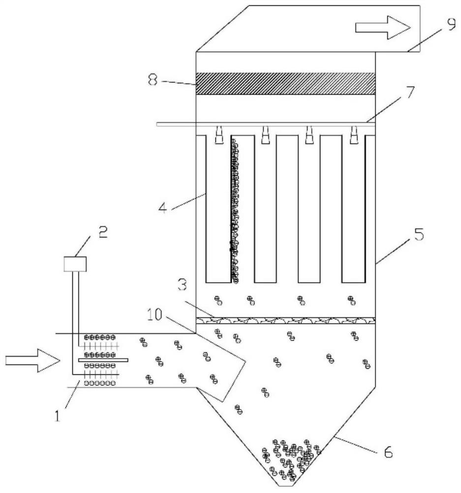
Image

Examples
Embodiment 1
[0042] The simulated flue gas volume is 200m 3 / h, flue gas temperature 350°C, filtration rate 1.2m / min, particle concentration in flue gas 500mg / m 3 , VOCs concentration 200mg / m 3 , Hg 0 Concentration 200μg / m 3 , the catalytic active components of the catalytic filter tube 4 include manganese oxides and vanadium oxides, and the mass percentage of the catalytic active components is 1%. Efficiency 93.1%, VOCs removal efficiency 60%, Hg 0 The removal efficiency is 50%.
Embodiment 2
[0044] The simulated flue gas volume is 200m 3 / h, flue gas temperature 350°C, filtration rate 1.2m / min, particle concentration in flue gas 500mg / m 3 , VOCs concentration 200mg / m 3 , Hg 0 Concentration 200μg / m 3 , the catalytic active component of the catalytic filter tube 4 includes manganese oxide and vanadium oxide, and the mass percentage of the catalytic active component is 1%. When the pulse power supply voltage is set to 20kV, the concentration of each pollutant at the exhaust gas outlet is tested, and the calculation is obtained Particulate matter removal efficiency 99.5%, VOCs removal efficiency 65%, Hg 0 The removal efficiency is 51.6%.
Embodiment 3
[0046] The simulated flue gas volume is 200m 3 / h, flue gas temperature 350°C, filtration rate 1.2m / min, particle concentration in flue gas 500mg / m 3 , VOCs concentration 200mg / m 3 , Hg 0 Concentration 200μg / m 3 , the catalytic active components of the catalytic filter tube 4 include manganese oxide and vanadium oxide, and the mass percentage of the catalytic active component is 1%. When the pulse power supply voltage is set to 100kV, the concentration of each pollutant at the exhaust gas outlet is tested, and the calculation is obtained Particulate matter removal efficiency 99.5%, VOCs removal efficiency 75%, Hg 0 The removal efficiency is 70.3%.
[0047] Table 1 Embodiment 1-3 process control parameters and effects
[0048] index Example 1 Example 2 Example 3 Power supply voltage (kV) 0 20 100 Filtration rate (m / min) 1.2 1.2 1.2 Active Components of Catalytic Filter Tubes manganese and vanadium oxides manganese and vanadium oxide...
PUM
 Abstract
Description
Claims
Application Information