Sulfur-containing gas desulfurization device system and method

A desulfurization device and gas technology, applied in the field of environmental engineering, can solve the problems of enhanced chemical oxidation of sulfides, decreased cell activity and desulfurization performance, and weakened organic sulfur inhibition, so as to reduce the formation of S2O32- and SO42- and achieve good application. Prospect, the effect of increasing the generation rate

Active Publication Date: 2021-06-04
INST OF PROCESS ENG CHINESE ACAD OF SCI
View PDF8 Cites 1 Cited by
  • Summary
  • Abstract
  • Description
  • Claims
  • Application Information

AI Technical Summary

Problems solved by technology

[0013] The thiol organic matter contains a sulfur group structure (-SH). -SH can break the disulfide bond in the molecule. RSH binds to the sulfide oxidase FCC of sulfur-oxidizing bacteria, thereby changing the structure of the enzyme, or binding to the enzyme's On the active site, the activity of the enzyme is reduced, resulting in a decrease in the oxidation activity of the cell, and the chemical oxidation of sulfide in the culture medium is enhanced. During the treatment process, the S 2 o 3 2- and SO 4 2- The yield increases, SO 4 2- and S 2 o 3 2- The accumulation of minerals increases the total salinity of the system. In order to cope with the rising environmental osmotic pressure, cells need to consume a lot of energy to produce a large amount of compatible solutes, which leads to the decline of cell activity and desulfurization performance.
[0014] Mercaptans are easily chemically reacted to form polythioethers, which are highly hydrophobic and easily adsorbed to sulfur particles, which weakens the inhibitory effect of organic sulfur

Method used


Image

  • Sulfur-containing gas desulfurization device system and method
  • Sulfur-containing gas desulfurization device system and method
  • Sulfur-containing gas desulfurization device system and method

Examples


Embodiment 1

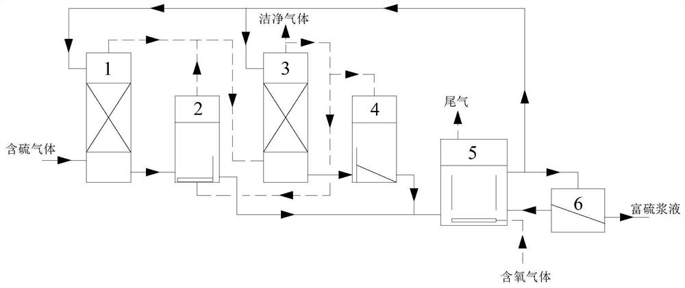
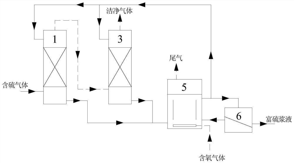
[0091] This embodiment provides a sulfur-containing gas desulfurization device system, the structural diagram of the sulfur-containing gas desulfurization device system is as follows figure 1 As shown, it includes biological purification tower, deep adsorption tower, tail gas removal tower, anaerobic conversion tower, biological regeneration tower and sulfur collection tower.

[0092] The liquid outlet of the biological purification tower is connected with the liquid inlet of the deep adsorption tower.

[0093] The liquid outlet of the tail gas removal tower is connected with the liquid inlet of the anaerobic conversion tower.

[0094] The liquid outlet of the deep adsorption tower and the liquid outlet of the anaerobic conversion tower are respectively independently connected with the liquid inlet of the biological regeneration tower.

[0095] The liquid outlet of the biological regeneration tower is independently connected with the liquid inlets of the biological purificati...


PUM


Abstract

The invention provides a sulfur-containing gas desulfurization device system and method. The device system comprises a biological purification device, a deep adsorption device, a tail gas removal device, an anaerobic conversion device, a biological regeneration device and a sulfur collection device. According to the device system, due to the arrangement of the tail gas removal device and the anaerobic conversion device, and organic sulfur in sulfur-containing gas reacts with sulfur particles to generate sulfide; then the sulfide is mixed with effluent of the deep adsorption tower and enters the biological regeneration tower, and the HS- is oxidized by sulfur oxidizing microorganisms under the oxygen-enriched condition to generate elemental sulfur, and the elemental sulfur is recycled. Compared with a traditional method, the method has the advantages that by adding an organic sulfur conversion process, inhibition of organic sulfur on the biological desulfurization process is effectively reduced, absorption of desulfurization bacteria on HS- and selection of HS- oxidation pathways are enhanced, formation of S2O3 < 2-> and SO4 < 2-> in the treatment process is reduced, and the generation rate of elemental sulfur is increased; the method has excellent economic benefits and application prospects.

Description

technical field [0001] The invention belongs to the technical field of environmental engineering and relates to a desulfurization device system, in particular to a sulfur-containing gas desulfurization device system and method. Background technique [0002] Desulfurization of natural gas and biogas can not only obtain clean gas, but also recover sulfur. Therefore, desulfurization of such gases is an important technical means that kills two birds with one stone and turns waste into treasure. However, natural gas and biogas often contain a large amount of sulfur compounds, such as hydrogen sulfide, mercaptans and sulfides. The above-mentioned sulfur-containing compounds are toxic and corrosive to a certain extent, and are more harmful to the environment; moreover, in the process of biological desulfurization, the organic sulfur in the sulfur-containing compounds will have a certain inhibitory effect on the activity of microbial cells, so that the desulfurization effect is grea...

Claims


Application Information

Patent Timeline
Patent Type & Authority Applications(China)
IPC IPC(8): B01D53/84B01D53/48B01D53/02
CPCB01D53/84B01D53/48B01D53/02B01D2257/302B01D2257/306Y02A50/20
Inventor 穆廷桢邢建民杨茂华苗得露赵胥浩
Owner INST OF PROCESS ENG CHINESE ACAD OF SCI
Why Eureka
Try Eureka