
Device and method for eliminating fluorescence interference in Raman spectrum by electrifying

A technology of Raman spectroscopy and Raman spectrometer, which is applied in the field of devices for eliminating fluorescence interference in Raman spectroscopy by electrification, can solve the problems that sample detection is helpless, cannot be applied, and such samples cannot be subjected to Raman detection, etc., and achieves elimination of fluorescence interference. Effect

Active Publication Date: 2021-06-04
SOUTH CHINA UNIV OF TECH
View PDF7 Cites 0 Cited by
  • Summary
  • Abstract
  • Description
  • Claims
  • Application Information

AI Technical Summary

Problems solved by technology

However, for bulk solid samples that cannot be made into powder, the above-mentioned patents cannot be applied; when the conventional method of quenching fluorescence cannot be effective under strong fluorescence interference, such samples will not be able to perform Raman detection
[0005] Most of the time, the reasons why conventional methods do not work are: 1. Due to the limitation of equipment conditions, the excitation wavelength cannot be changed. For example, the laboratory may only be equipped with common visible light lasers (including 785nm near-infrared lasers), 800nm ​​and above Laser or ultraviolet laser below 400nm is not equipped because it is too expensive
2. Although it is equipped with a near-infrared laser or an ultraviolet laser, since the signals of the near-infrared laser or ultraviolet laser are weak, the sample must be irradiated with a power 1-2 orders of magnitude higher than that of a visible light laser (such as 532nm). Get the ideal spectrum
However, if the sample is sensitive to heat and cannot be irradiated with high power, the detection of the sample will become helpless

Method used


Image

  • Device and method for eliminating fluorescence interference in Raman spectrum by electrifying
  • Device and method for eliminating fluorescence interference in Raman spectrum by electrifying
  • Device and method for eliminating fluorescence interference in Raman spectrum by electrifying

Examples


example 1

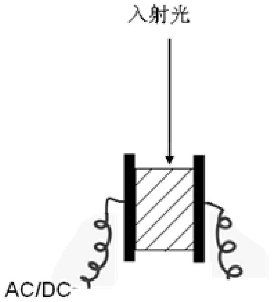
[0107] Sample 1 is a commercial 1.26 mm thick epoxy resin board (containing 50% calcium carbonate filler). Clamped by a pure silver plate electrode and applied with 220V DC, the electric field strength is 1.746×10 5 V / m.

[0108] Select a point close to the anode, and photobleach for 3 minutes after energizing for 17 minutes (keep energizing during photobleaching), and the total energizing time is 20 minutes. Then collect the Raman spectrum, the instrument conditions are: excitation wavelength 532nm, power to the sample 2mW, 50X telephoto lens, grating 600gr / mm, slit 400μm, pinhole 100μm, accumulation time 3s, accumulation 5 times.

[0109] The Raman spectra before and after power-on are as follows Figure 5 shown. It can be found that the fluorescence is very strong before electrification, and the signal is almost saturated. After electrification, the fluorescence was obviously weakened, and the fluorescence decreased by 63.39% according to the area under the curve. At t...

example 2

[0111]Sample 2 is a commercial 1.26 mm thick epoxy resin board (containing 50% calcium carbonate filler). It is clamped by stainless steel plate electrodes, and the commercial power is applied, that is, alternating current 220V, 50Hz. Then the peak electric field strength is 2.469×10 5 V / m.

[0112] Select a point in the middle of the sample, and then photobleach for 3 minutes after energizing for 37 minutes (keep energizing during photobleaching), and the total energizing time is 40 minutes. Then collect the Raman spectrum, the instrument conditions are: excitation wavelength 532nm, power to the sample 2mW, 50X telephoto lens, grating 600gr / mm, slit 400μm, pinhole 100μm, accumulation time 3s, accumulation 5 times.

[0113] The Raman spectra before and after power-on are as follows Figure 6 shown. It can be found that the fluorescence is very strong before electrification, and the signal is almost saturated. After electrification, the fluorescence is obviously weakened, ...

example 3

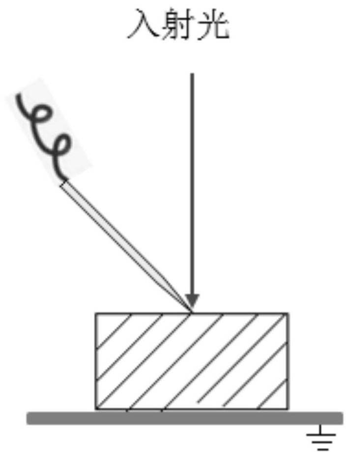
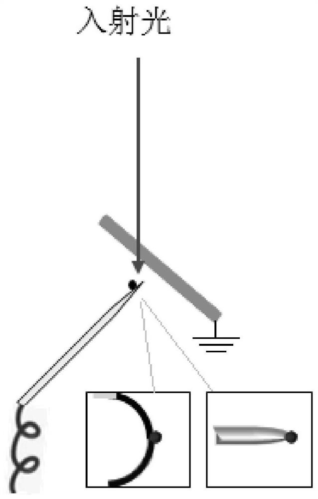
[0115] Sample 3 is lumpy amber. A stainless steel needle with a radius of curvature of 5 μm was used as the needle tip electrode to contact the bulk amber sample obliquely; the sample was placed on a pure copper substrate, and the substrate was grounded. The stainless steel needle is connected to the negative pole of the DC power supply through a wire, and the voltage is -220V.

[0116] Select a point at the tip of the needle, and then photobleach for 3 minutes after energizing for 12 minutes (keep energizing during photobleaching), and the total energizing time is 15 minutes. Then collect the Raman spectrum, the instrument conditions are: excitation wavelength 532nm, power to the sample 1mW, 50X telephoto lens, grating 600gr / mm, slit 400μm, pinhole 100μm, accumulation time 10s, accumulation 3 times.

[0117] The Raman spectra before and after power-on are as follows Figure 7 shown. It can be found that the fluorescence interference is very strong before electrification. ...


PUM

PropertyMeasurementUnit
Thicknessaaaaaaaaaa
Lengthaaaaaaaaaa
Widthaaaaaaaaaa

Abstract

The invention discloses a device and a method for eliminating fluorescence interference in Raman spectrum through electrification, the device comprises an electrode assembly and a Raman spectrometer, and the electrode assembly can adopt a plate electrode, a needle plate electrode or a needle net electrode. A sample to be detected is placed on a laser light path of the Raman spectrometer and located in an electric field generated by the electrode assembly or further formed ionic wind, and the device conducts Raman detection on the sample to be detected through the Raman spectrometer and collects a Raman spectrogram of the sample to be detected under the condition that the electric field or the ionic wind is externally applied. According to the invention, fluorescence in the Raman detection process can be quenched, so that fluorescence interference in the Raman detection process is eliminated, and a high-quality Raman spectrogram is obtained. The method has important application value in the fields of new materials, geology, jewelry, archaeological science, biomedicine, judicial expertise and the like.

Description

technical field [0001] The invention relates to the technical field of analysis and detection, in particular to a device and a method for eliminating fluorescence interference in Raman spectra by energizing. Background technique [0002] Indian physicist C.V.Raman reported a new phenomenon of visible light scattering in the journal Nature in 1928. When this scattering occurs, the frequency of the scattered light will change. This phenomenon is called Raman scattering. Raman was awarded the Nobel Prize in Physics in 1930 for his discovery of the Raman effect and Raman scattering. The Raman phenomenon is an inelastic scattering phenomenon of light. When a photon collides with a material molecule, the molecule generates an induced dipole moment under the action of an electromagnetic field to cause polarization, and energy transfer occurs between the molecule and the photon. This process can be performed with a Raman's "virtual energy level" to explain. The scattered light wit...

Claims


Application Information

Patent Timeline
IPC IPC(8): G01N21/65
CPCG01N21/65
Inventor 梁庆优龚湘君邓春林张广照杨贤锋刘俊宋国胜崔洁
Owner SOUTH CHINA UNIV OF TECH
Learn More