Optical fiber structure for temperature detection, manufacturing method and temperature detection system

A technology of optical fiber structure and manufacturing method, which is applied in the field of detection, can solve the problems of limited application environment and application prospects, large influence of thermistor temperature, weak anti-interference ability, etc., achieve good application prospects and development value, and improve evanescent field , the effect of solid structure

Pending Publication Date: 2021-06-25
ZHEJIANG NORMAL UNIVERSITY
View PDF0 Cites 0 Cited by
  • Summary
  • Abstract
  • Description
  • Claims
  • Application Information

AI Technical Summary

Problems solved by technology

Due to the low detection accuracy, long response time, weak anti-interference ability and the thermistor itself is greatly affected by temperat

Method used


Image

  • Optical fiber structure for temperature detection, manufacturing method and temperature detection system
  • Optical fiber structure for temperature detection, manufacturing method and temperature detection system
  • Optical fiber structure for temperature detection, manufacturing method and temperature detection system

Examples


Example Embodiment

[0029] Example 1:

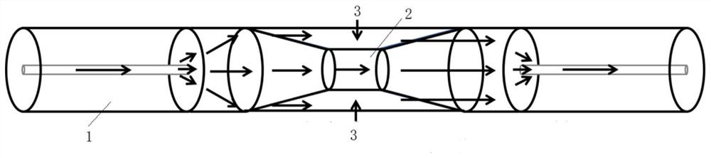
[0030] like figure 1 As shown, the embodiment of the present disclosure provides an optical fiber structure for temperature detection, mainly including two single-mode optical fibers 1 and a coreless optical fiber 2 arranged between the two single-mode optical fibers, wherein the coreless optical fiber 2 and the Two single-mode optical fibers 1 are placed coaxially, and the two ends of the coreless optical fiber 2 in the length direction are respectively fixed together with the two single-mode optical fibers.

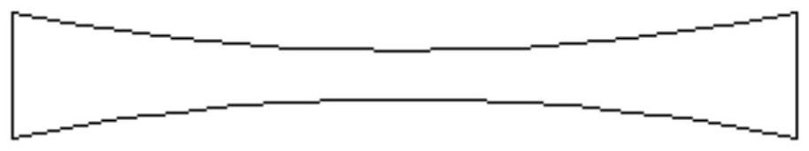
[0031] like figure 2 As shown, the coreless fiber is tapered into a structure with a thin center and thick ends. Preferably, the diameter of the middle part of the coreless fiber is equal to the radius of a single single-mode fiber, which is convenient for practical fiber welding.

[0032] In this embodiment, the two ends of the coreless fiber in the length direction are welded together with the ends of the single-mode fiber respectively.

[0033...

Example Embodiment

[0037] Example 2:

[0038] The following describes in detail the method for manufacturing the above-mentioned optical fiber structure for temperature detection, the method includes the following process:

[0039] Step 1: Splice the two ends of the untapered coreless fiber with the end of the single-mode fiber respectively to form a cascaded structure through the fusion splicing equipment, and then put the coreless fiber forming the cascaded structure on the fusion splice On the equipment, the two ends of the wireless optical fiber or the end of the single-mode fiber are respectively clamped by the two clamping pieces of the fusion splicing equipment, and the stepper motor connected to the clamping pieces is controlled by the controller in the fusion splicing equipment to move along the coreless fiber The axis line pulls the fiber slowly at a constant speed, and finally forms a structure with a thin middle and thick ends.

[0040] In the second step, a capillary quartz tube is...

Example Embodiment

[0043] Example 3

[0044] The following describes in detail the temperature detection system or device comprising the above-mentioned optical fiber structure, such as Figure 4 As shown, the detection device mainly includes ASE (broadband light source) equipment 4 , the optical fiber structure 5 , wide and narrow optical filters 6 , PIN tube 7 , amplifier circuit 8 , acquisition card 9 and computer 10 .

[0045]One end in the length direction of the optical fiber structure 5 is connected to the ASE device (broadband light source) 4, and the other end is connected to a suitable central wavelength (such as Image 6 The narrow-band optical filter 6 of 1577nm shown in the vertical line in the) is sent to PIN tube 7. exist Image 6 Among them, the light intensity at 1577nm changes with the change of temperature (the movement of the interference spectrum). As the temperature increases, the light intensity gradually increases, and each temperature corresponds to a specific light in...


PUM


Abstract

The invention relates to an optical fiber structure for temperature detection, a manufacturing method and a temperature detection system, and belongs to the technical field of detection. The structure mainly comprises two single-mode optical fibers and a coreless optical fiber arranged between the two single-mode optical fibers. The coreless optical fiber is arranged to be of a structure with the middle thin and the two ends thick, and the coreless optical fiber and the two single-mode optical fibers are coaxial. The two ends of the coreless optical fiber in the length direction are respectively welded with the end parts of the single-mode optical fibers, a capillary quartz tube sleeves the coreless optical fiber, the middle parts of the capillary quartz tube and the coreless optical fiber are filled with polydimethylsiloxane, and two ends of the capillary quartz tube in the length direction are respectively connected with the single-mode optical fibers in a sealing manner.

Description

technical field [0001] The disclosure belongs to the technical field of detection, and in particular relates to an optical fiber structure and a manufacturing method for temperature detection and a temperature detection system. Background technique [0002] The statements herein merely provide background information related to the present disclosure and do not necessarily constitute prior art. [0003] The precise detection and control of temperature is of vital significance in industrial production, aerospace, food processing, biomedicine, etc. Due to the problems of low detection accuracy, long response time, weak anti-interference ability and the thermistor itself is greatly affected by temperature, the application environment and application prospects of traditional electrical temperature sensors in the market are greatly limited. Contents of the invention [0004] Aiming at the technical problems existing in the prior art, the present disclosure provides an optical f...

Claims


Application Information

Patent Timeline
IPC IPC(8): G01K11/32G02B6/02
CPCG01K11/32G02B6/02395
Inventor 彭保进马倩倩王梦娇王增辉
Owner ZHEJIANG NORMAL UNIVERSITY
Why Eureka
Try Eureka