
A battery system and its assembly method

A battery system and assembly method technology, applied in secondary batteries, chemical instruments and methods, circuits, etc., can solve the problems of high battery operating temperature, hidden safety hazards, and increased hazard, achieve thermally induced flexibility, and improve use safety. , the effect of reducing the contact thermal resistance

Active Publication Date: 2022-07-05
JINAN UNIVERSITY
View PDF12 Cites 0 Cited by
  • Summary
  • Abstract
  • Description
  • Claims
  • Application Information

AI Technical Summary

Problems solved by technology

The thermal conductivity of paraffin (PA) is about 0.2W m -1 ·K -1 , and will become liquid when the temperature is higher than the melting point, there is a serious leakage problem
In addition, the battery installation and integration problems caused by the rigidity of phase change materials will lead to high thermal resistance at the contact interface with the battery. If the thermal resistance is too high, the operating temperature of the battery will be too high, which will not only affect the performance of the battery, but also pose a great safety hazard. Hidden danger
In particular, for cylindrical batteries, it is difficult to effectively match the curved surface characteristics with phase change materials
The existing related assembly method is to first open a hole slightly larger than the outer diameter of the battery on the bulk phase change material, and then insert the battery into the hole, but in this way, the battery and CPCM (CPCM is a composite phase change material, is It is made by blending fatty acid esters and advanced aliphatic alcohol phase change materials at a mass ratio of 95:5), and there is no close contact between them, so there is inevitably a large thermal resistance
Thermally conductive adhesive can be filled in the pores, but still suffers from uneven coating, increased space and economic costs
For prismatic batteries, when cooperating with phase change materials, in order to compress the phase change materials and batteries, the same compression device is often used to form a unit with a large number of batteries. However, the energy density of prismatic batteries is large. When a thermal safety accident occurs to one of the batteries, it will affect a large number of other batteries through heat transfer, and the hazard will be greatly increased.

Method used


Image

  • A battery system and its assembly method
  • A battery system and its assembly method

Examples


Embodiment 1

[0046] Example 1: Assembly of the battery system

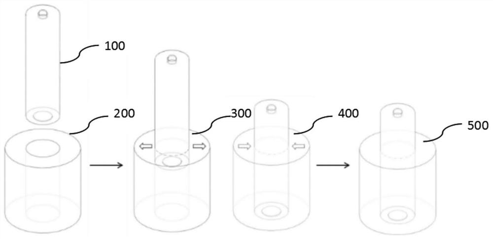
[0047] A battery system includes a composite phase change material and a battery; the composite phase change material, by mass fraction, comprises 76% of paraffin wax, 19% of olefin block copolymer and 5% of expanded graphite; Interference fit; the battery is a cylindrical battery, the battery type is 18650.

[0048] The assembling method of the above battery system includes the following steps:

[0049] (1) Preparation of composite phase change material: heating paraffin and olefin block copolymer to 160°C and mixing, then gradually adding expanded graphite, stirring for 30 minutes to obtain a molten mixture, and then placing the molten mixture in a stainless steel mold (cylindrical) for molding, the molding pressure is 1kN / m 2 , the molding time is 10 minutes, cooled to room temperature (for example, 20 ° C), continued molding for 10 minutes, and then stripped to obtain a cylindrical composite phase change material;

[00...

Embodiment 2

[0053] Example 2: Assembly of the battery system

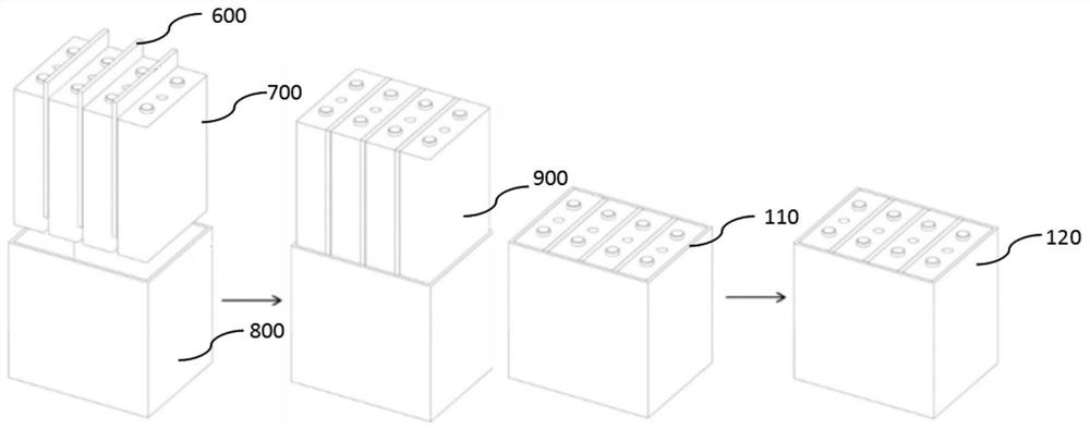
[0054] A battery system includes a composite phase change material and a battery; the composite phase change material, by mass fraction, comprises 88% of paraffin, 10% of an olefin block copolymer and 2% of expanded graphite; the composite phase change material and the battery are used between Interference fit; cells are square cells.

[0055] The assembling method of the above battery system includes the following steps:

[0056] (1) Preparation of composite phase change material: heating paraffin and olefin block copolymer to 158°C and mixing, then gradually adding expanded graphite, stirring for 30 minutes to obtain a molten mixture, and then placing the molten mixture in a stainless steel mold (sheet) for molding, and the molding pressure is 1 kN / m 2 , the molding time is 10 minutes, cool to room temperature (for example, 20 ° C), continue molding for 10 minutes, and then release the film to obtain a sheet-like composite...

Embodiment 3

[0059] Example 3: Assembly of the battery system

[0060] Compared with Example 2, the only difference in Example 3 is that a plurality of battery cells are assembled into a plurality of through holes of a block-shaped composite phase change material at the same time, and a certain gap is left between the plurality of battery cells. The voids are filled by the composite phase change material, and the battery and the composite phase change material in each battery cell can also obtain a pressing force to maintain a close fit.


PUM

PropertyMeasurementUnit
melt flow indexaaaaaaaaaa

Abstract

The invention belongs to the technical field of batteries, and discloses a battery system and an assembling method thereof. The battery system includes a composite phase-change material and a battery; the composite phase-change material includes a phase-change material and an olefin block copolymer; and an interference fit is used between the composite phase-change material and the battery. The composite phase change material used in the present invention includes a phase change material, such as paraffin wax, and an olefin block copolymer, wherein the olefin block copolymer is a supporting material, which can achieve thermal flexibility and prevent leakage of the liquid phase change material. The composite phase change material and the battery are assembled by means of interference fit, which greatly reduces the contact thermal resistance between the battery and the composite phase change material, greatly reduces the temperature during the working process of the battery, and not only improves the electrical performance of the battery during the working process. , but also significantly improve the safety of battery use.

Description

technical field [0001] The invention belongs to the technical field of batteries, and particularly relates to a battery system and an assembling method thereof. Background technique [0002] Li-ion batteries are widely used in electrochemical energy storage systems as energy storage devices due to their advantages in key performance such as energy density and operating voltage. The working mechanism and performance of the battery show a high dependence on temperature, and maintaining the battery within a suitable temperature range can maintain the optimal working performance. The battery will generate a certain amount of heat during the working process, so it is necessary to discharge the heat reasonably to avoid heat accumulation and affect the battery voltage, charge and discharge efficiency, cycle life and the safety of the battery. [0003] The battery thermal management system based on the phase change material can effectively control the working temperature of the bat...

Claims


Application Information

Patent Timeline
Patent Type & Authority Patents(China)
IPC IPC(8): H01M10/613H01M10/653H01M10/659C09K5/06
CPCH01M10/613H01M10/653H01M10/659C09K5/063Y02P20/141Y02E60/10
Inventor 吴伟雄马瑞鑫庄师强张贤
Owner JINAN UNIVERSITY
Learn More