Thermoelectric conversion backflow solar energy-saving system

An energy-saving system and thermoelectric conversion technology, which is applied in the field of environmental pollution treatment, can solve problems such as huge floor area, increased investment cost and operating cost, and instability, so as to reduce investment cost and operating cost, and make up for the difficulty of waste heat recovery. The effect of resolving unstable

Pending Publication Date: 2021-08-20
台山市红岭洗染有限公司
View PDF0 Cites 0 Cited by
  • Summary
  • Abstract
  • Description
  • Claims
  • Application Information

AI Technical Summary

Problems solved by technology

However, solar energy itself is an intermittent energy source, and its energy flow density is low, discontinuous, and unstable; these characteristics of solar energy make it difficult to meet the energy demand of drying kinetics of sludge and other materials, thus directly affecting the popularization and application of solar drying technology
If the sludge solar drying technology only relies on solar radiation heat, the required land area is extremely large, and it is greatly affected by the season. In the case of low winter temperature and weak solar radiation intensity, the drying rate drops significantly, resulting in Unstable processing power
Heat pump drying technology is an energy-saving drying technology that can recover sensible heat and latent heat of water vapor from drying waste gas. Therefore, the existing sludge drying technology combines solar technology with heat pump drying technology to form a solar heat pump combined sludge drying technology. Drying technology, which can overcome the shortcomings of a single solar heat source, and can reduce the energy consumption of sludge drying, so heat pumps or solar collector systems are often used to generate hot water to accelerate sludge drying through floor heating, while general geothermal sources Heat pumps, water source heat pumps, and air source heat pumps have high power consumption due to low source heat temperature, which increases investment costs and operating costs

Method used


Image

  • Thermoelectric conversion backflow solar energy-saving system
  • Thermoelectric conversion backflow solar energy-saving system

Examples


Embodiment Construction

[0024] In order to make the purpose, technical solutions and advantages of the embodiments of the present invention clearer, the technical solutions in the embodiments of the present invention will be clearly and completely described below in conjunction with the drawings in the embodiments of the present invention. Obviously, the described embodiments It is a part of embodiments of the present invention, but not all embodiments. The components of the embodiments of the invention generally described and illustrated in the figures herein may be arranged and designed in a variety of different configurations.

[0025] Accordingly, the following detailed description of the embodiments of the invention provided in the accompanying drawings is not intended to limit the scope of the claimed invention, but merely represents selected embodiments of the invention. Based on the embodiments of the present invention, all other embodiments obtained by persons of ordinary skill in the art wi...


PUM


Abstract

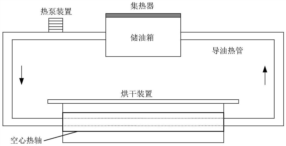
The invention discloses a thermoelectric conversion backflow solar energy-saving system. The energy-saving system comprises a heat pump device, a drying device, a heat supply device and a thermoelectric converter. The heat supply device receives solar radiation energy and transmits the solar radiation energy to an oil storage tank, oil in the oil storage tank absorbs heat collected by a solar heat collector, the temperature rises, then the oil is conveyed into a drying device under the action of an oil pump to heat air, and the air dries wet sludge under the accelerated flow of a fan; and the thermoelectric converter recovers and converts waste heat of the drying device into electric energy, and operation can be maintained through the electric energy under the condition of poor weather. Therefore, waste heat wasted by the treatment system is recovered, the defects of high waste heat recovery difficulty and high energy consumption of a solar drying auxiliary heat source are overcome, the problems of unstable solar drying capability, low treatment speed and large occupied area are solved, the heat energy utilization rate of the whole sludge treatment system is obviously improved, and the investment cost and the operation cost of sludge treatment are greatly reduced.

Description

technical field [0001] The invention relates to the technical field of environmental pollution treatment, in particular to a solar energy-saving system for thermoelectric conversion backflow. Background technique [0002] Sludge is a solid sediment produced in the process of water and sewage treatment. It is an extremely complex heterogeneous body composed of organic debris, bacterial cells, inorganic particles, and colloids. The main characteristics of sludge are high water content, which can be as high as 99%, high organic matter content, easy to rot and smell, and fine particles, small specific gravity, and colloidal liquid state. With the acceleration of urbanization in my country, the rate of urban sewage treatment has increased year by year, and the sludge output of urban sewage treatment plants has also increased sharply. Untreated sludge entering the environment will directly cause secondary pollution to water bodies and the atmosphere, posing a serious threat to th...

Claims


Application Information

Patent Timeline
Patent Type & Authority Applications(China)
IPC IPC(8): C02F11/131F24S20/40F24S80/30
CPCC02F2201/009C02F2303/10C02F11/131F24S20/40F24S80/30Y02E10/40
Inventor 黄灿阳
Owner 台山市红岭洗染有限公司
Why Eureka
Try Eureka