
Positive plate, manufacturing method thereof and battery

A positive electrode sheet and a positive electrode current collector technology are applied to the positive electrode sheet and its manufacturing method, and the battery field, which can solve the problems of low production turnover efficiency, diving cycle life, elongated production cycle, etc., so as to improve the turnover efficiency and improve the liquid absorption speed. , the effect of accelerating the infiltration speed

Inactive Publication Date: 2021-08-20
FPR CONNECTIVITY TECH INC
View PDF10 Cites 2 Cited by
  • Summary
  • Abstract
  • Description
  • Claims
  • Application Information

AI Technical Summary

Problems solved by technology

[0005] In the production process of the battery cell, a standing time is required after the liquid injection process, usually 1 to 3 days, to ensure that the electrolyte is infiltrated and the electrode sheet is fully absorbed. Otherwise, the battery cell will have low capacity, large internal resistance, and cycle life diving. , poor consistency and other issues
This standing time will lengthen the production cycle, resulting in low production turnover efficiency

Method used


Image

  • Positive plate, manufacturing method thereof and battery
  • Positive plate, manufacturing method thereof and battery
  • Positive plate, manufacturing method thereof and battery

Examples


Embodiment 1

[0054] A slurry coating is evenly coated on a copper foil to form a graphite negative electrode sheet, and the copper foil may be, for example, 8 microns thick.

[0055] Rolling the graphite negative electrode sheet comprising the copper foil and the second coating, the thickness of the rolled graphite negative electrode sheet is 0.097 mm, wherein the negative active material in the second coating is The content is 97%.

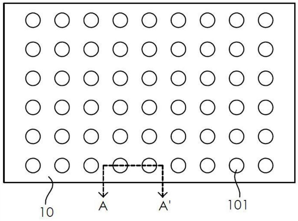
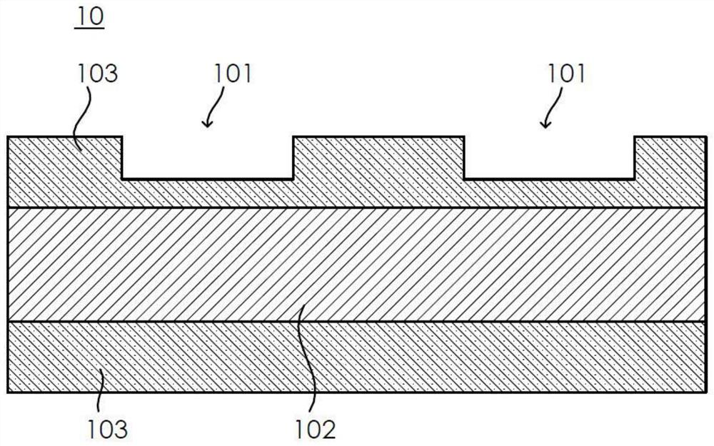
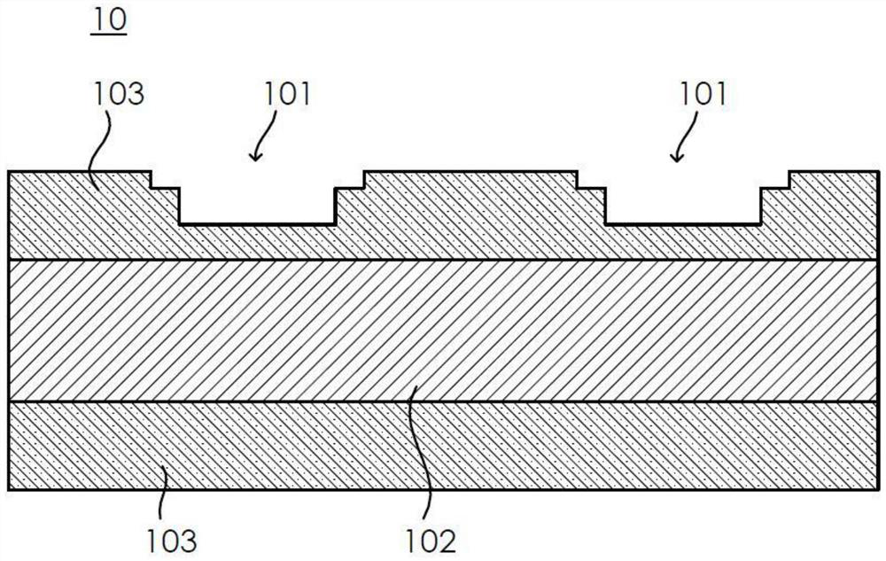
[0056] Carry out laser dot matrix drilling (the depressed portion 101) to the graphite negative plate, the wavelength of the laser is 355nm, the pulse power is 3 watts, the pulse repetition frequency is 20 kHz, the pulse width is 25 nanoseconds, and the pulse The number is 5, and to form the aperture (the diameter of the smallest circumscribed circle of the shape corresponding to the opening of the recessed portion 101) is 15 microns, and the hole depth (the depth of the recessed portion 101) is 30 microns, adjacent holes The pitch (the distance between the ...

Embodiment 2

[0061] Embodiment 2 is similar to embodiment 1, the difference is:

[0062] The pulse power of the laser is 2 watts, the pulse repetition frequency is 20 kHz, the pulse width is 10 nanoseconds, and the number of pulses is 5, so as to form an aperture with a diameter of 5 microns, a hole depth of 30 microns, and a distance between adjacent holes of 0.5 mm matrix round holes.

Embodiment 3

[0064] Embodiment 3 is similar to any of the foregoing embodiments, except that:

[0065] The pulse power of the laser is 4 watts, the pulse repetition frequency is 20 kilohertz, the pulse width is 30 nanoseconds, and the number of pulses is 5, so that the aperture is 30 microns, the hole depth is 30 microns, and the distance between adjacent holes is 0.5 mm matrix round holes.


PUM

PropertyMeasurementUnit
diameteraaaaaaaaaa
depthaaaaaaaaaa
diameteraaaaaaaaaa

Abstract

The embodiment of the invention discloses a positive plate, a manufacturing method thereof and a battery. The positive plate comprises a positive current collector and a coating arranged on the surface of the positive current collector, the surface of the coating of the positive plate is provided with at least four concave parts, the at least four concave parts are arranged in a two-dimensional array form, and the depth of the concave parts is smaller than the thickness of the coating. According to the embodiment of the invention, the charging and discharging performance of the battery in a low-temperature environment can be improved.

Description

technical field [0001] The present application relates to the field of battery technology, in particular to a positive electrode sheet, a manufacturing method thereof, and a battery. Background technique [0002] Lithium-ion batteries have quickly become one of the most widely used energy storage products due to their high operating voltage and long cycle life. However, lithium-ion batteries also have certain disadvantages. For example, when winter comes, lithium-ion batteries are prone to power outages and cannot work. The reason is that in low-temperature environments, lithium-ion batteries have voltage drops, low discharge capacity, and capacity decay. Fast, poor magnification performance and so on. [0003] Lithium battery charging is a process in which lithium ions are extracted from the positive electrode, migrate through the electrolyte, and intercalate into the negative electrode material. In a low-temperature environment, the chemical reactivity decreases, and the...

Claims


Application Information

Patent Timeline
Patent Type & Authority Applications(China)
IPC IPC(8): H01M4/13H01M4/139H01M10/058H01M10/0525H01M10/42
CPCH01M4/13H01M4/139H01M10/058H01M10/0525H01M10/4235Y02P70/50Y02E60/10
Inventor 周攀刘承香
Owner FPR CONNECTIVITY TECH INC
Learn More