Microfocus field emission electron source based on carbon nanotubes and preparation method thereof

A technology of carbon nanotubes and carbon nanotube cathodes, which is applied in the field of field emission electron sources, can solve the problem that the focus size of micro-focus X-ray sources is not small enough

Active Publication Date: 2021-09-10
WENZHOU UNIVERSITY
View PDF10 Cites 1 Cited by
  • Summary
  • Abstract
  • Description
  • Claims
  • Application Information

AI Technical Summary

Problems solved by technology

However, compared with the tip size of carbon nanotubes, the focal spot size of the microfocus X-ray source is still far from small enough

Method used


Image

  • Microfocus field emission electron source based on carbon nanotubes and preparation method thereof
  • Microfocus field emission electron source based on carbon nanotubes and preparation method thereof
  • Microfocus field emission electron source based on carbon nanotubes and preparation method thereof

Examples


Embodiment Construction

[0030] In order to make the object, technical solution and advantages of the present invention clearer, the present invention will be further described in detail below in conjunction with the accompanying drawings.

[0031] Preparation Examples:

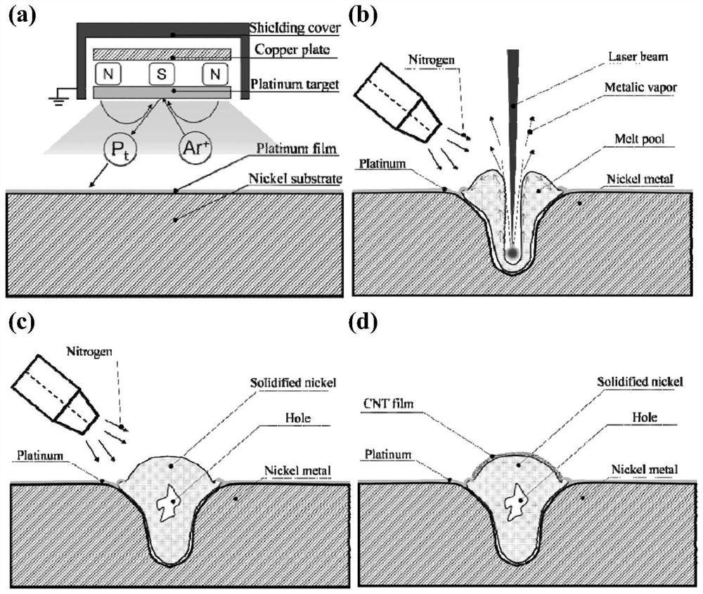
[0032] In the preparation of the carbon nanotube cathode, a layer of metal platinum (vacuum degree: 9Pa, sputtering current: 30mA, sputtering time: 600s) was first plated on the surface of the nickel substrate by magnetron sputtering, such as figure 1 (a). Then the nickel substrate is spot ablated with negative defocus by pulsed laser (wavelength: 1064nm, frequency: 3Hz, output current: 50-150A, negative defocus distance: 0.00-0.50mm). Negative defocusing ablation of pulsed laser can make the internal particles of nickel metal melt and erupt to the surface to form a spherical shell, such as figure 1 b and 1c are shown. During negative defocus ablation, the laser focus is inside the material, which melts the nickel metal inside, an...


PUM

PropertyMeasurementUnit
diameteraaaaaaaaaa

Abstract

The invention discloses a microfocus field emission electron source based on a carbon nanotube and a preparation method thereof. According to the technical scheme, the preparation method comprises the following steps: (1) plating a metal platinum layer on the surface of a nickel substrate; (2) under the protection of protective gas, performing point ablation on the surface of the nickel substrate plated with metal platinum by using pulse laser in a negative defocusing mode, wherein the laser focus is in the nickel substrate during negative defocusing ablation, so that internal nickel metal is molten, and the molten nickel metal flows to the surface of the nickel substrate under the pushing action of nickel metal steam and is cooled to form a spherical shell; and (3) directly growing a carbon nanotube cathode film on the spherical shell formed by laser ablation of the nickel substrate by using a chemical vapor deposition method. According to the invention, the microfocus electron source has the advantages of low starting electric field (less than 1V / [mu] m), high current density (about 1A / cm<2>), good high-pressure emission working stability and the like.

Description

technical field [0001] The invention relates to a field emission electron source, in particular to a carbon nanotube-based micro-focus field emission electron source and a preparation method thereof. Background technique [0002] Carbon nanotube (CNT) has excellent physical, chemical, structural and other properties, and is an ideal field emission cathode material. Compared with traditional metal tip (usually tungsten or molybdenum) emitters, it has a tip that is almost close to the theoretical limit. Surface area, its tip size is only a few nanometers to tens of nanometers, has a low field emission voltage (can be less than 100 volts), can transmit a large current density, and the current is stable and has a long service life, so it is very suitable as an excellent The point electron source is used in the electron emission components of scanning electron microscope (Scanning Electron Microscope), transmission electron microscope (Transmission Electron Microscope), micro-foc...

Claims


Application Information

Patent Timeline
Patent Type & Authority Applications(China)
IPC IPC(8): H01J37/073H01J9/02
CPCH01J37/073H01J9/025
Inventor 祝维董长昆钱维金黄卫军
Owner WENZHOU UNIVERSITY
Why Eureka
Try Eureka