
Organic electroluminescent device

An electroluminescent element and electroluminescent technology, applied in electrical elements, luminescent materials, organic chemistry, etc., can solve problems such as insufficient, low driving voltage luminous efficiency, and reduced element characteristics.

Pending Publication Date: 2021-09-14
HODOGOYA CHEMICAL CO LTD
View PDF13 Cites 0 Cited by
  • Summary
  • Abstract
  • Description
  • Claims
  • Application Information

AI Technical Summary

Problems solved by technology

Although NPD has good hole transport ability, its glass transition temperature (Tg), which is an indicator of heat resistance, is as low as 96°C, and crystallization under high temperature conditions degrades device characteristics (see, for example, Non-Patent Document 4)
In addition, among the aromatic amine derivatives described in the above-mentioned patent documents, it is known that the mobility of a hole is 10. -3 cm 2 Compounds with excellent mobility above / Vs (for example, refer to Patent Document 1 and Patent Document 2), but due to insufficient electron barrier properties, part of the electrons pass through the light-emitting layer, and improvement in luminous efficiency cannot be expected. Higher efficiency requires materials with higher electron barrier properties, more stable thin films, and high heat resistance
In addition, aromatic amine derivatives with high durability are disclosed (for example, refer to Patent Document 3), but there is no example of using a substance used as a charge transport material for an electrophotographic photoreceptor as an organic EL element.
[0011] As compounds with improved properties such as heat resistance and hole injection properties, arylamine compounds having a substituted carbazole structure have been proposed (for example, refer to Patent Document 4 and Patent Document 5), but when these compounds are used in space In the elements of the hole injection layer and the hole transport layer, although the heat resistance and luminous efficiency have been improved, they are still not sufficient, and further lower driving voltage and higher luminous efficiency are required.

Method used


Image

  • Organic electroluminescent device
  • Organic electroluminescent device
  • Organic electroluminescent device

Examples


Embodiment 1

[0227]

[0228] 22.4 g of 4-(naphthalen-1-yl)aniline, 19.8 g of 3-bromobiphenyl, 12.2 g of sodium tert-butoxide, and 230 mL of toluene were added to a nitrogen-substituted reaction vessel, and nitrogen gas was blown in while irradiating ultrasonic waves for 30 minutes. 0.8 g of tris(dibenzylideneacetone)dipalladium and 0.5 g of 2,2'-bis(diphenylphosphine)-1,1'-binaphthyl were added, heated, and stirred at 110°C for 16 hours. After removing insoluble matter by filtration, the filtrate was concentrated. The residue was purified by column chromatography to obtain 25.4 g (yield 75.6%) of 4-(naphthalen-1-yl)phenyl-biphenyl-3-amine as a light yellow viscous substance.

[0229] 23.9 g of 4-(naphthalen-1-yl)phenyl-biphenyl-3-amine and 240 mL of dimethylformamide were added to the nitrogen-substituted reaction vessel, and cooled in an ice bath. 11.6 g of N-bromosuccinimide was added in portions over 30 minutes, followed by stirring at 5° C. for 4 hours. Water was added, extracted w...

Embodiment 2

[0238]

[0239] Add (1,1':2',1"-terphenyl-4'-yl)amine 17.2g, 2-(4-bromophenyl)naphthalene 18.0g, tert-butoxy Sodium 9.2g, toluene 270mL, while irradiating ultrasonic waves for 30 minutes, pass nitrogen gas. Add tris(dibenzylideneacetone) dipalladium 1.2g, 2,2'-bis(diphenylphosphine)-1,1'-bis 0.8 g of naphthalene was heated and stirred at 110° C. for 16 hours. After removing the insolubles by filtration, the filtrate was heated, and at 80° C., adsorption purification using activated clay and silica gel was carried out, and heating and filtration was carried out. The filtrate was concentrated and passed through toluene-heptyl The residue was purified by recrystallization in alkanes to obtain {4-(naphthalene-2-yl)phenyl}-(1,1':2',1"-terphenyl-5'-yl)amine as a yellow-white powder Body 24.3g (yield 85.4%).

[0240] Add 24.3 g of {4-(naphthalene-2-yl)phenyl}-(1,1':2',1"-terphenyl-5'-yl)amine, 9-bromo 15.4g of phenanthrene, 10.4g of sodium tert-butoxide, 240mL of toluene, while i...

Embodiment 3

[0247]

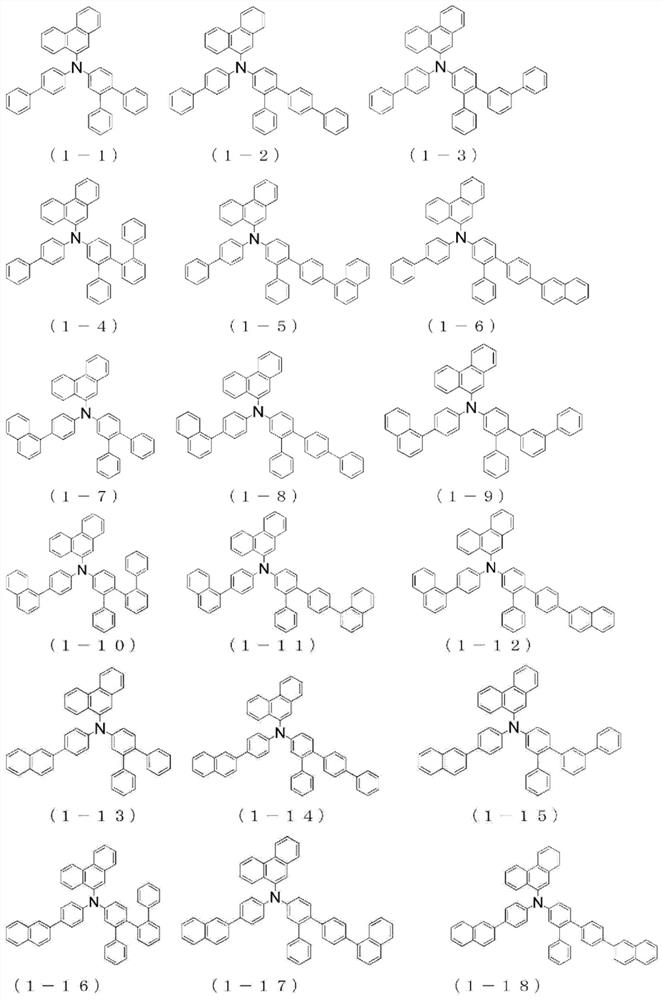
[0248] The {4"-(naphthalene-1-yl)-1,1':2',1"-terphenyl-5'-yl}-{4-(naphthalene-1-yl)phenyl group of Example 1 } amine to {4"-(naphthalen-1-yl)-1,1':2',1"-terphenyl-5'-yl}-{4-(naphthalen-2-yl)phenyl} Amines, the same procedure was performed to give {4-(naphthalene-2-yl)phenyl}-(phenanthrene-9-yl)-{4"-(naphthalene-1-yl)-1,1':2', 4.9 g of white powder of 1"-terphenyl-5'-yl}amine (compound 1-17) (yield 40%).

[0249] The structure of the obtained white powder was identified using NMR.

[0250] use 1 H-NMR (CDCl 3 ) detected the following 39 hydrogen signals.

[0251] δ(ppm)=8.76-8.86(2H), 8.24-8.28(1H), 8.06(1H), 7.85-7.95(8H), 7.36-7.78(19H), 7.19-7.31(8H).

[0252] [chem 21]

[0253]


PUM

PropertyMeasurementUnit
glass transition temperatureaaaaaaaaaa

Abstract

The object of the invention is to provide a material for a highly efficient and highly durable organic EL device, the material having excellent hole injection / transport capability, electron-blocking ability, thin film stability, and durability, and to further provide an organic EL device having high efficiency, low driving voltage, and long service life by combining the material and various organic EL device materials having excellent hole injection / transport capability, electron-blocking ability, thin film stability, and durability, such that the properties of each material can be effectively exhibited. The arylamine compound having a specific structure according to the invention has excellent hole injection / transport capability, thin film stability, and durability, and can thus be selected as a material for a hole transport layer that efficiently transports holes injected from the positive electrode side. Moreover, various organic EL devices obtained by combining materials such as the electron transport material having a specific structure exhibit good device characteristics.

Description

technical field [0001] The present invention relates to an organic electroluminescent element as a self-luminescent element suitable for various display devices, and in detail, relates to an organic electroluminescent element (hereinafter, simply referred to as an organic EL element) using a specific arylamine compound. . Background technique [0002] Since the organic EL element is a self-luminous element, it is brighter than a liquid crystal element, has excellent visibility, and can realize a clear display, so it has been actively studied. [0003] In 1987, C.W.Tang of Eastman Kodak Company developed a laminated structural element in which each material shared various functions, thus making the organic EL element using organic materials a practical element. They laminated a phosphor capable of transporting electrons and an organic substance capable of transporting holes, injected the charges of the two into the phosphor layer to make it emit light, and obtained 1000 cd / m...

Claims


Application Information

Patent Timeline
Patent Type & Authority Applications(China)
IPC IPC(8): C09K11/06H01L51/50
CPCC09K11/06H10K85/626H10K85/633H10K85/615H10K85/6574H10K50/156H10K50/15H10K2101/90H10K85/655H10K85/631H10K85/654C07C2603/26C07C211/61C07D307/91C09K2211/1007C09K2211/1011C09K2211/1014C09K2211/1018H10K85/636H10K50/11H10K50/16H10K50/155H10K2101/10
Inventor 骏河和行山本刚史望月俊二平山雄太林秀一
Owner HODOGOYA CHEMICAL CO LTD
Learn More