
Water purification treatment system for high-iron-manganese-silicon water source

A technology of water purification and manganese-silicon, which is applied in the field of water treatment, can solve the problems of low removal rate of silicon ions, no self-cleaning system, and drop of effluent pH value, so as to meet engineering design requirements, simple water treatment process, and The effect of small area

Pending Publication Date: 2021-09-24
SINOPEC NINGBO ENG +2
View PDF0 Cites 0 Cited by
  • Summary
  • Abstract
  • Description
  • Claims
  • Application Information

AI Technical Summary

Problems solved by technology

[0007] The main problems in the existing water purification treatment process for groundwater are as follows: 1) At present, the silicon removal methods in water mainly include chemical coagulation, ion exchange, and ultrafiltration. Use the adsorption, coagulation or flocculation of certain metal oxides or hydroxides and silicon to achieve the purpose of silicon removal. The removal rate of silicon ions in the above methods is not high (about 65%), and the pH value of the effluent drops significantly. 2) There are many existing water treatment systems, but most of them have defects such as high cost, mediocre filtering effect, and no self-cleaning system, and the clean water obtained by directly filtering groundwater does not meet the standard of tap water, and further disinfection is required. Meet the use standard of tap water; 3) Groundwater in some areas contains iron and manganese exceeding the standard, some iron content is as high as 20-30mg / L, and some manganese content exceeds 2mg / L. When the alkalinity of water is low, the solubility When the silicic acid is high, the air natural oxidation method has little effect on iron removal

Method used


Image

  • Water purification treatment system for high-iron-manganese-silicon water source

Examples


Embodiment Construction

[0030] The present invention will be further described in detail below in conjunction with the accompanying drawings and embodiments.

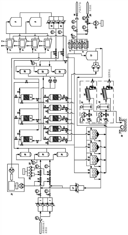
[0031] The water purification treatment system of the high iron manganese silicon water source of embodiment, as figure 1 As shown, it includes a primary lift pump 1, a primary pipeline mixer 31, a primary contact tank 51, an aeration contact oxidizer 6, an electrocoagulation facility 8, an electrocoagulation outlet tank 9, a secondary lift pump 10, and a secondary pipeline Mixer 32, secondary contact tank 52, filter 7, backwash unit, ultraviolet sterilizer 11, dosing unit, clarified water tank 12 and sludge dehydration unit, backwash unit includes backwash water tank 13 and booster pump 14. The dosing unit includes a sodium hypochlorite dosing device 21, a first sodium hydroxide dosing device 22, a second sodium hydroxide dosing device 23 and a flocculant dosing device 24, and the sludge dehydration unit includes a sludge mixing tank 15 and ...


PUM


Abstract

The invention discloses a water purification treatment system for a high-iron-manganese-silicon water source. The water purification treatment system comprises a first-stage lifting pump, a first-stage pipeline mixer, a first-stage contact tank, a gas-liquid mixing pump, an aeration contact oxidizer, an electric flocculation facility, an electric flocculation water outlet tank, a second-stage lifting pump, a second-stage pipeline mixer, a filter, a backwashing unit, an ultraviolet sterilization device and a dosing unit, the backwashing unit comprises a backwashing water tank and a pressure pump, and the dosing unit comprises a sodium hypochlorite dosing device, a first sodium hydroxide dosing device and a second sodium hydroxide dosing device. The treatment system is simple in composition, low in cost and concise in water treatment process, solves the problems of removal, disinfection and the like of iron, manganese and silicon in underground water raw water, has a good purification effect on the high-iron-manganese-silicon underground water raw water, the purified effluent meets the sanitary requirement of drinking water, and the finally treated water can be used as product production water and living water. The treatment system is small in occupied area, convenient to move, capable of meeting engineering design requirements and convenient to operate and use.

Description

technical field [0001] The invention relates to the technical field of water treatment, in particular to a water purification treatment system for high-iron-manganese-silicon water sources where raw water is high-iron-manganese-silicon groundwater. Background technique [0002] Using groundwater as the source of domestic water and production water must face the unique water quality treatment problems of groundwater, that is, excessive silicon, iron, and manganese elements caused by geological structures, and some bacterial pollution. [0003] GB 5749-2006 "Drinking Water Hygienic Standards" stipulates that the limit values ​​of iron and manganese in drinking water are 0.3mg / L and 0.1mg / L respectively. [0004] Although the limit value of silicon is not specified in the GB 5749-2006 standard, studies have shown that focal glomerulonephritis and individuals with significantly increased silicon content in kidney tissue have been found in people with a high-silicon diet; long-te...

Claims


Application Information

Patent Timeline
Patent Type & Authority Applications(China)
IPC IPC(8): C02F9/08C02F11/14C02F11/12C02F103/06C02F101/10C02F101/20
CPCC02F9/00C02F11/14C02F11/12C02F1/001C02F1/32C02F1/463C02F1/76C02F1/50C02F1/66C02F2103/06C02F2301/08C02F2303/14C02F2303/16C02F2101/203C02F2101/206C02F2101/10C02F2303/04C02F2303/20
Inventor 陈景玉杨力
Owner SINOPEC NINGBO ENG
Learn More