
Fine control method for removing SO3 through base injection

A refined control, base technology, applied in chemical instruments and methods, separation methods, indirect carbon dioxide emission reduction, etc., can solve the problems of lack of continuous operation and implementation cases, gaps in refined control processes, etc.

Active Publication Date: 2021-10-08
SUZHOU XIRE ENERGY SAVING ENVIRONMENTAL PROTECTION TECH CO LTD +1
View PDF5 Cites 2 Cited by
  • Summary
  • Abstract
  • Description
  • Claims
  • Application Information

AI Technical Summary

Problems solved by technology

Some domestic power plants have installed SO 3 Adsorption removal device, but there is a lack of implementation cases of continuous operation, for the removal of SO by base injection 3 The refined control process is even more blank

Method used


Image

  • Fine control method for removing SO3 through base injection
  • Fine control method for removing SO3 through base injection
  • Fine control method for removing SO3 through base injection

Examples


Embodiment 1

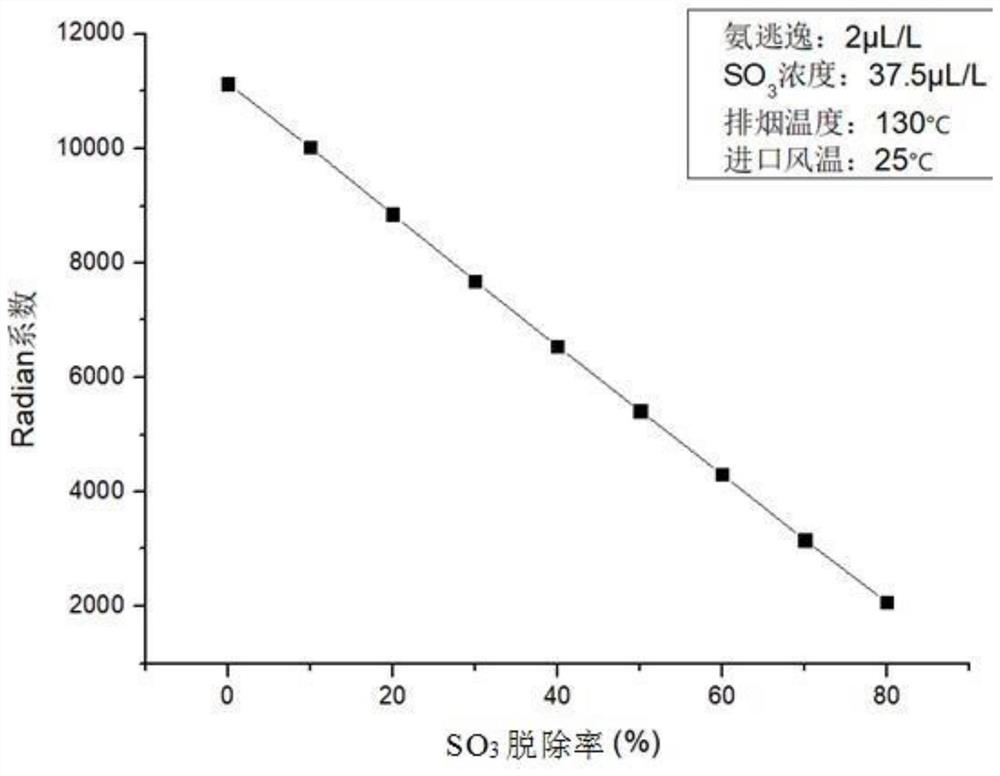
[0060] When the coal-fired unit is running at full load, the inlet flue of the air preheater is preferentially selected as the base absorbent injection point; it is difficult to control the escape of ammonia during full-load operation, and the higher the flue gas temperature is, the higher the catalyst’s effect on SO 2 / SO 3 The conversion rate is also higher, that is, the Radian deposition coefficient of the air preheater is high under full load conditions, and the risk of clogging is high. Taking the full-load flue gas working condition of a coal-fired unit as an example, as figure 2 The deposition coefficient of the air preheater and SO 3 The relationship curve of the removal rate, under this working condition, the deposition coefficient of the air preheater is controlled within 6000, the SO 3 The removal rate needs to be above 36%. According to this SO 3 The removal rate guides the operation of the base absorbent injection device, and the injection can reach more than...

Embodiment 2

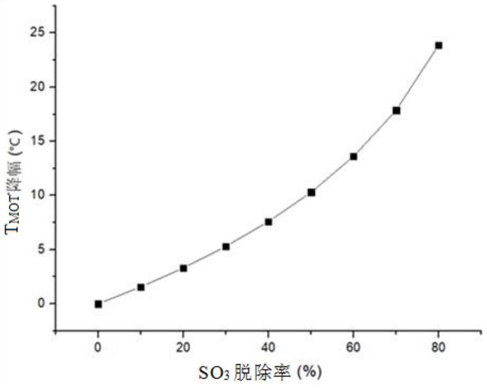
[0062] At low load, the flue temperature at the SCR inlet is likely to be lower than the MOT, that is, at low load, the SCR inlet flue is preferentially selected as the base absorbent injection point. Firstly, according to the smoke temperature difference, that is, according to the strategy corresponding to the case where the SCR inlet flue is the base absorbent injection point, determine the SCR inlet SO 3 Removal rate; according to the SO 3 For the removal rate, the base absorbent injection device is put into operation at the SCR inlet flue; after the operation, when the MOT drop meets the catalyst operation requirements, continue to calculate the air preheater deposition coefficient according to the flue gas parameters at the air preheater, if the The deposition coefficient has met the critical value requirement, and the base absorbent injection device is not put into operation at the inlet flue of the air preheater; if it is greater than the critical value, set the corresp...


PUM


Abstract

The invention discloses a fine control method for removing SO3 through base injection. The fine control method specifically comprises the following steps: selecting a base absorbent injection point according to the requirements of a coal-fired unit; determining an SO3 removal rate control strategy according to the selected base absorbent injection point, specifically, when the base absorbent injection point is an SCR inlet flue, comparing the SCR inlet smoke temperature with the lowest continuous ammonia injection temperature of the SCR denitration equipment, and determining the SO3 removal rate and the corresponding base absorbent injection amount according to the comparison result; and when the base absorbent injection point is the inlet flue of an air pre-heater, firstly determining the deposition coefficient critical value of the air pre-heater according to the unit load of a coal-fired unit, and then determining the SO3 removal rate corresponding to the deposition coefficient critical value of the air pre-heater according to the relationship between the deposition coefficient critical value of the air pre-heater and the SO3 removal rate. Corresponding quantification targets can be formulated according to different SO3 removal requirements, and fine operation of the base injection system is guided.

Description

technical field [0001] The invention relates to the removal of SO by base injection in coal-fired boilers 3 technical field, in particular to a base jet removal of SO 3 fine-grained control method. Background technique [0002] SO in flue gas of coal-fired boiler 3 Concentration is the main factor that limits the minimum ammonia injection temperature of the denitrification catalyst, and it is also the main cause of clogging of ABS in tail facilities (such as air preheater, low temperature economizer, etc.). [0003] for SO 3 Absorbent injection removal technology can generally be used for the removal of denitrification or air preheater inlet and outlet flue, spraying alkaline substances such as slaked lime, magnesium hydroxide, sodium bisulfite, sodium carbonate, and SO 3 A selective reaction occurs to remove SO 3 . Some domestic power plants have installed SO 3 Adsorption removal device, but there is a lack of implementation cases of continuous operation, for the rem...

Claims


Application Information

Patent Timeline
IPC IPC(8): B01D53/50B01D53/86B01D53/90B01D53/56B01D53/78
CPCB01D53/504B01D53/8631B01D53/90B01D2258/0283Y02E20/34
Inventor 梁俊杰宋玉宝谢新华方朝君赵宁波
Owner SUZHOU XIRE ENERGY SAVING ENVIRONMENTAL PROTECTION TECH CO LTD
Learn More