Differential type metal particle drying device

A metal particle and drying device technology, which is applied in the direction of drying gas arrangement, granular material drying, non-progressive dryer, etc., can solve the problems of difficult uniform contact of metal powder, easy agglomeration of metal powder, and affecting drying efficiency, etc., to achieve Improve drying uniformity, facilitate aggregation, and good dispersion effect

Active Publication Date: 2021-10-22
南通江勤美金属制品有限公司
View PDF6 Cites 2 Cited by
  • Summary
  • Abstract
  • Description
  • Claims
  • Application Information

AI Technical Summary

Problems solved by technology

[0003] Due to the small particle size of the metal powder, it is easy to absorb moisture, so it needs to be dried before sintering and other processing processes. In the prior art, it is generally dried by contacting with hot air, but in the actual drying process, even In the rotating drying cylinder, it is also difficult for the metal powder to contact with the hot air evenly, which affects the drying efficiency, and the metal powder with high humidity is prone to agglomeration

Method used


Image

  • Differential type metal particle drying device
  • Differential type metal particle drying device
  • Differential type metal particle drying device

Examples


Embodiment 1

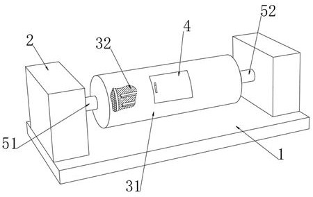
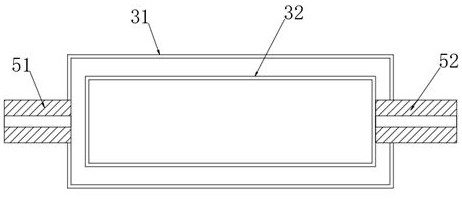
[0045] see Figure 1-2 , a differential speed metal particle drying device, comprising a bottom plate 1 and two positioning boxes 2 fixedly connected to the left and right upper ends of the bottom plate 1 respectively, a differential speed drying cylinder is connected between the two positioning boxes 2, and the differential speed drying cylinder includes a The outer powder transfer cylinder 31 and the inner powder transfer cylinder 32 located on the inner side, the outer end of the powder transfer cylinder 31 is fixed with a sealing door 4, a positioning box 2 and the powder transfer cylinder 31 are connected with an outer rotating shaft 51 through an electric rotating shaft, and An inner shaft 52 is connected between a positioning box 2 and the inner powder barrel 32 through an electric shaft. The powder transfer barrel 31 moves through the inner shaft 52. The outer shaft 51 and the inner shaft 52 are both tubular structures. The outer shaft 51 corresponds to the positioning ...

Embodiment 2

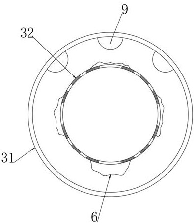
[0054] see Figure 10-11 The outer end of the throwing powder touch bar 9 is fixedly connected with a magnetron bisexual sheet, and the magnetron bisexual sheet includes an air sheet layer 101 fixedly connected with the outer end of the fixed magnetic sheet 91 and a plurality of throwing pads fixedly connected to the air sheet layer 101. Powder magnetic strip 102, a plurality of powder throwing magnetic strips 102 are not in contact with each other, and compressed inert gas is filled between the powder throwing strip 9 and the magnetron bisexual sheet, and the air sheet layer 101 is coated with LINE-X paint on the surface The elastic sealing structure of the coating is made, so that the wear resistance and tensile resistance of the air sheet layer 101 are enhanced, so that it is not easy to be damaged when it is continuously hit by the pocket cloth 6 .

[0055] The powder throwing touch strip 9 is an electromagnet, and the powder throwing touch strip 9 is electrically connecte...


PUM

PropertyMeasurementUnit
sizeaaaaaaaaaa

Abstract

The invention discloses a differential type metal particle drying device, and belongs to the field of drying, according to the differential type metal particle drying device, through the arrangement of a differential drying cylinder, in the interval rotation process of the differential drying cylinder, metal powder continuously enters pocket cloth and is rapidly gathered under the action of centrifugal force, therefore, the pocket cloth extends outwards and collides with a powder throwing collision strip, on one hand, caked metal powder is effectively broken and eliminated through collision, compared with the prior art, the caking rate of the metal powder is remarkably reduced, on the other hand, during collision, the metal powder in the pocket cloth is thrown out under the action of collision force and is quickly dispersed outwards, the metal powder is always in a dispersed dynamic state, meanwhile, the dispersion range is expanded, so that the full contact between the differential type metal particle drying device and the metal powder is remarkably improved, and the drying efficiency and the drying uniformity are greatly improved.

Description

technical field [0001] The invention relates to the field of drying, more specifically, to a differential-speed metal particle drying device. Background technique [0002] Metal powder refers to a group of metal particles whose size is less than 1mm. Including single metal powder, alloy powder and some refractory compound powder with metallic properties, it is the main raw material of powder metallurgy. Elemental metals are generally silver-white, and when the metal is under certain conditions, it is a black powder. Most metal powders are black. [0003] Due to the small particle size of the metal powder, it is easy to absorb moisture, so it needs to be dried before sintering and other processing processes. In the prior art, it is generally dried by contacting with hot air, but in the actual drying process, even In the rotating drying cylinder, it is also difficult for the metal powder to be in uniform contact with the hot air flow, which affects the drying efficiency, an...

Claims


Application Information

Patent Timeline
Patent Type & Authority Applications(China)
IPC IPC(8): F26B11/04F26B21/00F26B25/04F26B25/16
CPCF26B11/0413F26B21/001F26B21/004F26B25/04F26B25/16F26B2200/08
Inventor 叶勤明朱海雷
Owner 南通江勤美金属制品有限公司
Why Eureka
Try Eureka