Wireless optical communication data transmission device and method

A data transmission device and wireless optical communication technology, applied in the field of optical communication, can solve problems such as fixed receiving position, adjustment of interference, and limitation of light source modulation bandwidth, so as to improve position flexibility, efficiently use bandwidth, and reduce system complexity Effect

Active Publication Date: 2021-10-22
SUZHOU UNIV
View PDF5 Cites 2 Cited by
  • Summary
  • Abstract
  • Description
  • Claims
  • Application Information

AI Technical Summary

Problems solved by technology

However, in wireless optical communication, there is no mature wireless optical module supporting M-PAM, which limits the rate of digital baseband transmission in wireless optical communication.
[0003] Existing visible light communication light source lamps for PAM modulation convert serial input control signals into parallel output signals through serial-to-parallel converters, and emit PAM signals by lighting different numbers of lamp beads. However, in the drive circuit , the lighting and extinguishing of different lamp beads have different delay times, which limits the modulation bandwidth of the light source, making the transmitter unsuitable for high-speed M-PAM communication, and the light source lamp depends on the position angle of the receiver. If the receiver If the angular position changes, the received light intensity is not linearly proportional to the number of lighted lamp beads, which increases the complexity of the receiver
There is also a clock data recovery circuit for a PAM4 receiver with a waveform screening function, and the PAM4 receiver forms a clock data recovery circuit body through a comparator and a phase detector. The reference threshold voltage of the comparator is fixed, so that its receiving position can only be fixed , and is easily affected by external adjustment interference, and cannot be adaptively adjusted

Method used


Image

  • Wireless optical communication data transmission device and method
  • Wireless optical communication data transmission device and method
  • Wireless optical communication data transmission device and method

Examples


Embodiment 1

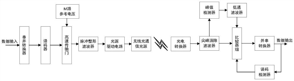
[0025] refer to figure 1 , an embodiment of the present invention provides a wireless optical communication data transmission device, including a transmitting module and a receiving module;

[0026] The transmitting module includes a transmission gate, and the transmitting module is used to convert the serial data into multiple control signals to control the transmission gate to output electrical signals, and convert the electrical signals into optical signals and transmit them to the receiving module;

[0027] The receiving module includes a peak detector and a comparator group. The receiving module is used to convert the received optical signal into an electrical signal and output serial data after the threshold judgment of the comparator group. The peak detector is based on the received electrical signal. The comparator group provides a reference voltage, and the comparator group performs voltage division according to the reference voltage to determine the threshold.

[00...

Embodiment 2

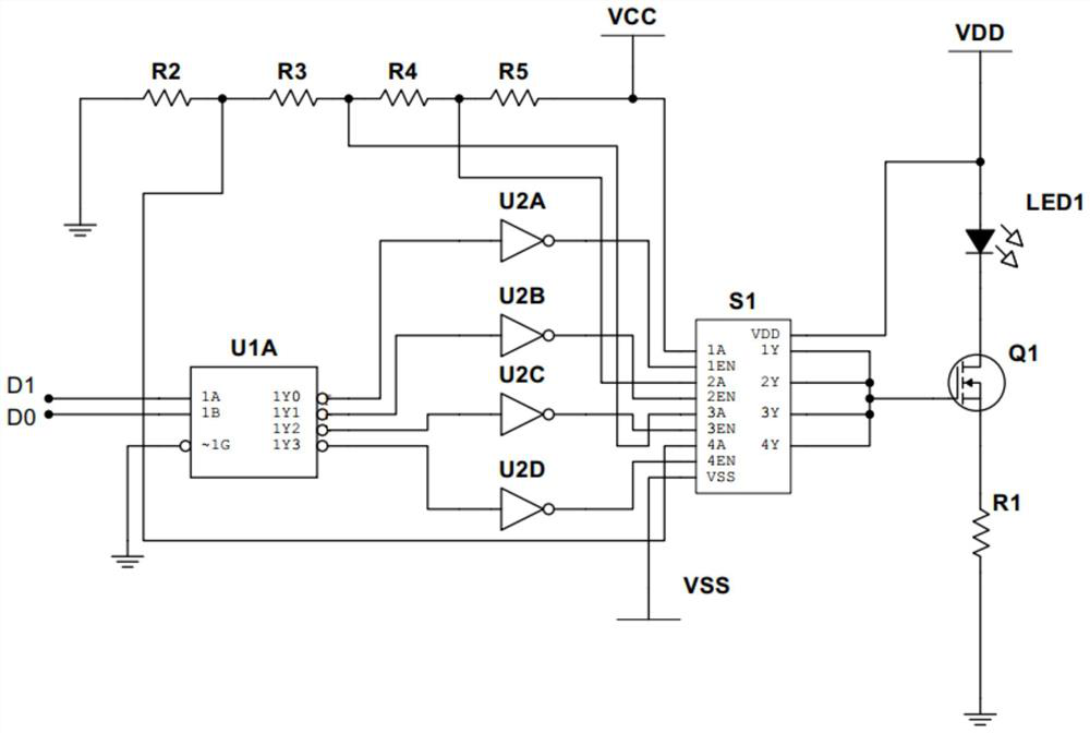
[0032] refer to figure 1 with figure 2 , the embodiment of the present invention provides a wireless optical communication data transmission device, on the basis of Embodiment 1, wherein the transmitting module performs circuit design, such as figure 2As shown, U1A is a 2-4 decoder, U2A, U2B, U2C, and U2D are 4 inverters, S1 is a 4-way transmission gate, Q1 is a driving MOS tube, R1 is a current-limiting resistor, and light source 1 is a light-emitting diode . The input of the serial data and the serial-to-parallel converter can be implemented by the sequential circuit in the FPGA, and finally output two parallel digital signals of D1 and D0. After passing through the U1A decoder, the corresponding voltage in the transmission gate is gated to the drive tube Q1. The driving tube Q1 provides driving current for the light source LED1. The transmission gate reference voltage is supplied by V CC It is provided by voltage division of resistors R2, R3, R4, and R5. Among them, t...

Embodiment 3

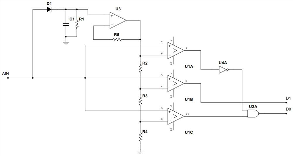
[0034] refer to figure 1 with image 3 , the embodiment of the present invention provides a wireless optical communication data transmission device, on the basis of Embodiment 1, wherein the receiving module performs circuit design, such as image 3 As shown, AIN is the electrical signal passed through the peak elimination filter, U1A, U1B, and U1C form a comparator group, D1, C1, and R1 form a peak detection circuit, and the U3 operational amplifier and R2, R3, and R4 are divided into a comparator group The threshold value is provided, and U4A and U2A output parallel two-way digital signals D1 and D0 according to the comparison results, and send them to subsequent sequential circuits for parallel-to-serial conversion processing. The method of dynamically adjusting the decision threshold by the peak detector and the comparator group can reduce the influence of the communication distance and the position on the communication in the wireless optical communication, and improve t...


PUM


Abstract

The invention discloses a wireless optical communication data transmission device and method. The wireless optical communication data transmission device comprises a transmitting module and a receiving module, wherein the transmitting module comprises a transmission gate and is used for converting serial data into multiple control signals to control the transmission gate to output an electric signal, converting the electric signal into an optical signal and transmitting the optical signal to the receiving module; the receiving module comprises a peak detector and a comparator group; the receiving module is used for converting a received optical signal into an electric signal and outputting serial data after the threshold judgment by the comparator group; the peak detector provides a reference voltage for the comparator group according to the received electric signal, and the comparator group performs voltage division according to the reference voltage to determine a threshold value. The device is not limited by a distance transmission environment, the stability and the mobility of wireless optical communication are enhanced, and the bandwidth utilization rate can be improved through high-order PAM.

Description

technical field [0001] The invention relates to the field of optical communication, in particular to a wireless optical communication data transmission device and method. Background technique [0002] With the development of 5G and big data technology, people have a higher demand for network speed. For the non-return-to-zero (NRZ) modulation method currently used in the mainstream, only 1 bit of information can be transmitted in one symbol period, so in order to achieve a higher communication rate, a higher bandwidth is required, and it is very difficult to increase the bandwidth of existing optical devices . Therefore, the multi-level pulse amplitude modulation (M-PAM) high-order modulation method will support the optical interconnection to move towards a higher rate. In optical fiber communication, pulse amplitude modulation PAM4 has been widely used, and there are relatively mature PAM4 optical modules. In wireless optical communication, due to the limitation of the ba...

Claims


Application Information

Patent Timeline
Patent Type & Authority Applications(China)
IPC IPC(8): H04B10/54
CPCH04B10/541H04B10/291
Inventor 熊超然由骁迪姜子乐沈纲祥
Owner SUZHOU UNIV
Why Eureka
Try Eureka