Converter with replaceable furnace bottom and construction method for primary masonry

A construction method and converter technology, applied in the manufacture of converters, etc., can solve the problem of easy adhesion and combination of joint materials and furnace body refractory materials, joint material and furnace body refractory materials are not easy to separate, and affect the construction efficiency of furnace bottom heat replacement and other problems, to achieve the effect of easy disassembly and cleaning, good high temperature strength and performance, and ensuring construction quality

Pending Publication Date: 2021-11-16
JINAN LUDONG REFRACTORY CO LTD
View PDF9 Cites 3 Cited by
  • Summary
  • Abstract
  • Description
  • Claims
  • Application Information

AI Technical Summary

Problems solved by technology

[0003] In the process of BOF bottom-blowing oxygen smelting, the life of the refractories at the bottom of the BOF is difficult to be synchronized with the life of the refractory materials in the furnace body. The refractories are replaced by heat, so the treatment quality and construction method of the joint between the furnace bottom refractories and the furnace body refractories are particularly important when the converter is first built. Inadequate filling of seam material reduces the service life of the converter, and is prone to phenomena such as pulverization, falling off, erosion, and steel breakout; second, when the furnace bottom is hot replaced, it will be found that the joint material used for the initial masonry and the refractory material of the furnace body are easily damaged. Adhesion and bonding make the joint material and the refractory material of the furnace body difficult to separate and difficult to clean, which affects the construction efficiency of the heat replacement of the furnace bottom. This is a problem in the existing technology

Method used


Image

  • Converter with replaceable furnace bottom and construction method for primary masonry

Examples


Embodiment 1

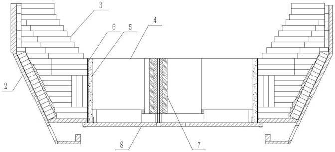
[0032] A converter with a replaceable bottom, such as figure 1 As shown, it includes a detachable converter bottom shell 8 and a converter body shell 2, the furnace body refractory material 3 is built on the inner side of the converter body shell 2, and the furnace bottom refractory material 4 is built on the converter bottom shell 8, The converter bottom shell 8 is detachably fixed on the converter body shell 2 by bolts, an annular gap is formed between the furnace body refractory material 3 and the furnace bottom refractory material 4, and the furnace body refractory material 3 is in the annular gap An isolation layer 6 is pasted on the vertical surface on one side.

[0033] As a preferred embodiment, the isolation layer 6 is aluminum foil paper, the thickness of the aluminum foil paper is 0.025mm, and the width of the annular gap is between 30-100mm. Sewing material5.

[0034] As a preferred embodiment, a gas supply and powder injection system 7 runs through between the c...

Embodiment 2

[0037] A converter with a replaceable bottom, such as figure 1 As shown, it includes a detachable converter bottom shell 8 and a converter body shell 2, the furnace body refractory material 3 is built on the inner side of the converter body shell 2, and the furnace bottom refractory material 4 is built on the converter bottom shell 8, The converter bottom shell 8 is detachably fixed on the converter body shell 2 by bolts, an annular gap is formed between the furnace body refractory material 3 and the furnace bottom refractory material 4, and the furnace body refractory material 3 is in the annular gap An isolation layer 6 is pasted on the vertical surface of one side

[0038] As a preferred embodiment, the isolation layer 6 can also be made of glass fiber aluminum foil cloth, or pure cotton cloth, or carbon fiber cloth material, which can also isolate the adhesion between the furnace body refractory material and the ramming material. The converter is easy to disassemble and c...

Embodiment 3

[0040] The solid materials used in the ramming joint material in this example are 70wt% fused magnesia particles, 16wt% fused magnesia fine powder, 12wt% high iron and high calcium sand fine powder, 5wt% medium temperature asphalt fine powder, 1.2wt% Metal aluminum powder, 1.5wt% silicon carbide fine powder, 1.2wt% solid resin, and 3.6wt% washing oil as liquid material.

[0041] As a preferred embodiment, the content of MgO in the fused magnesia particles is 97wt%, and the particle size is 3mm; the content of MgO in the fine powder of fused magnesia is 97wt%, and the particle size is 0.08mm; The content of MgO in fine powder is 85wt%, Fe 2 o 3 The content of CaO is 6wt%, the content of CaO is 10wt%, and its particle size is 0.08mm; the softening point of medium-temperature asphalt fine powder is 115°C, the residual carbon content is 58%, and the particle size is 0.8mm; Al in metal aluminum powder The content of SiC in silicon carbide fine powder is 99wt%, and the particle si...


PUM

PropertyMeasurementUnit
thicknessaaaaaaaaaa
widthaaaaaaaaaa
particle diameteraaaaaaaaaa

Abstract

The invention discloses a converter with a replaceable furnace bottom and a construction method for primary masonry. The converter comprises a converter bottom shell and a converter body shell which are detachable, a converter body refractory material is built on the inner side of the converter body shell, a converter bottom refractory material is built on the converter bottom shell, the converter bottom shell is connected to the converter body shell, an annular gap is formed between the converter body refractory material and the converter bottom refractory material, an isolating layer is pasted on the vertical surface, on one side of the annular gap, of the converter body refractory material, the annular gap is filled with a special ramming joint material when the converter is constructed for the first time, and the isolating layer isolates adhesion and combination between the converter body refractory material and the ramming joint material. Therefore, when the converter bottom is subjected to hot replacement, the refractory material of the converter body and the ramming material are very easy to separate and easy to disassemble and clean, the construction efficiency of the converter bottom hot replacement is improved, the joint material is filled and tamped in multiple layers, the construction quality is ensured, the erosion speed of molten steel to the joint material is slowed down, and the service life of the converter during primary masonry is greatly prolonged.

Description

technical field [0001] The invention relates to the field of smelting equipment, in particular to a converter with a replaceable furnace bottom and a construction method for primary masonry. Background technique [0002] The converter is mainly used to produce carbon steel, alloy steel and smelt copper and nickel, and is currently the most commonly used steelmaking equipment. With the improvement of my country's iron and steel smelting technology, the smelting method of converter bottom blowing oxygen + powder spraying has gradually been valued by iron and steel enterprises. The oxygen bottom blowing converter blowing method can make the stirring intensity of the molten pool intense, and the oxygen flow can be evenly blown into the molten pool and the upper part. The slag layer has less influence on the reaction in the furnace, and the unexpected smelting effect and other excellent smelting characteristics can be obtained by spraying iron ore powder or the mixture of returned...

Claims


Application Information

Patent Timeline
Patent Type & Authority Applications(China)
IPC IPC(8): C04B35/043C21C5/44
CPCC04B35/043C21C5/44C21C5/441C04B2235/3826C04B2235/402C04B2235/77C04B2235/9607
Inventor 吕仁祥刘在春王之龙纪怀杰李庆涛刘吉良
Owner JINAN LUDONG REFRACTORY CO LTD
Why Eureka
Try Eureka