Novel integrated microbial fuel cell for leachate treatment

A technology of fuel cells and microorganisms, applied in the field of new integrated microbial fuel cells, can solve the problems of low operating costs, high mass transfer resistance, high cost membranes, etc., to reduce consumption and waste, realize regeneration, and reduce the area occupied by the device Effect

Active Publication Date: 2021-12-10
上海交通大学重庆研究院
View PDF5 Cites 0 Cited by
  • Summary
  • Abstract
  • Description
  • Claims
  • Application Information

AI Technical Summary

Problems solved by technology

The double-chamber structure is the most classic, it is convenient to manage the cathode and anode separately, but there is a large distance between the cathode chamber and the anode chamber, the mass transfer resistance is high, the ion exchange membrane is expensive and needs to be replaced frequently, and its cost is too high and long-term After operation, it will cause problems such as membrane fouling and ion deposition
In practical sewage treatment applications, anaerobic microbial fuel cells have wide application prospects due to their low operating costs, but the problems of methane recovery and utilization still need to be solved
A set of integrated single-mode coupled anammox and anaerobic methane denitrification microbial fuel cells were studied to solve the problems of expensive membrane materials, easy clogging, pollution and anaerobic methane recovery in dual-chamber microbial fuel cells

Method used


Image

  • Novel integrated microbial fuel cell for leachate treatment

Examples


Embodiment Construction

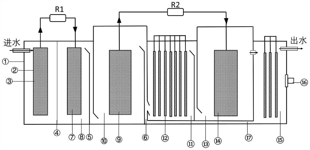
[0021] Such as figure 1 As shown, a new type of integrated microbial fuel cell for leachate treatment, including anaerobic No. 1 anode chamber 1, anaerobic No. 1 cathode chamber 8, anaerobic methane denitrification No. Oxygen ammonium oxidation chamber 11, anaerobic methane denitrification No. 2 cathode chamber 13 and nitrosation reaction chamber 15, anaerobic No. 1 anode chamber 1 is provided with a water inlet on the left side, anaerobic No. The electrode partitions are carried out between the chambers 8 through the cation exchange membrane 4, the protons are transferred with the flow state of the reactor through the baffle 5 between the anaerobic No. 1 cathode chamber 8 and the anaerobic methane denitrification No. Nitrification No. 2 anode chamber 10 and anammox chamber 11, and anammox chamber 11 and anaerobic methane denitrification No. 2 cathode chamber 13 are all connected by overflow channel 6, and nitrosation reaction chamber 15 is set There is a micro-aeration syste...


PUM


Abstract

The invention discloses a novel integrated microbial fuel cell for leachate treatment. The novel integrated microbial fuel cell is characterized in that a cation exchange membrane is arranged between an anaerobic anode chamber 1 and an anaerobic cathode chamber 1, a baffle is arranged between the anaerobic cathode chamber 1 and an anaerobic methane denitrification anode chamber 2, the anaerobic methane denitrification anode chamber 2 is connected with an anaerobic ammonia oxidation chamber through an overflow channel, the anaerobic ammonia oxidation chamber is connected with the anaerobic methane denitrification cathode chamber 2 through an overflow channel, a micro-aeration system is arranged in a nitrosation reaction chamber, an inner reflux tank is arranged at the bottom of the nitrosation reaction chamber, the inner reflux tank provides an electron acceptor for anaerobic ammonia oxidation and anaerobic methane denitrification through a reflux pipeline, the top of each electrode chamber is provided with an electrode jack and a reference electrode jack, and the electrode is made of a carbon felt electrode material. According to the invention, anaerobic oxidation, anaerobic ammonia oxidation and anaerobic methane denitrification can be synchronously realized, the consumption of cation exchange membranes is reduced, and advanced treatment of landfill leachate and regeneration of electric power resources are effectively realized.

Description

technical field [0001] The invention relates to the technical field of microbial fuel cells, in particular to a novel integrated microbial fuel cell for leachate treatment. Background technique [0002] Traditional microbial fuel cells for leachate treatment are mainly divided into single-chamber and double-chamber types. The Coulomb force of the single-chamber air cathode is relatively low, which restricts its actual production and use. The double-chamber structure is the most classic, it is convenient to manage the cathode and anode separately, but there is a large distance between the cathode chamber and the anode chamber, the mass transfer resistance is high, the ion exchange membrane is expensive and needs to be replaced frequently, and its cost is too high and long-term After operation, it will cause problems such as membrane fouling and ion deposition. In practical sewage treatment applications, anaerobic microbial fuel cells have wide application prospects due to th...

Claims


Application Information

Patent Timeline
IPC IPC(8): C02F3/00C02F3/28H01M8/16C02F101/16C02F101/30
CPCC02F3/005C02F3/286C02F3/2866H01M8/16C02F2101/16C02F2101/30Y02E60/50
Inventor 楼紫阳王辉王景耿涌赵天涛刘伟张千
Owner 上海交通大学重庆研究院
Why Eureka
Try Eureka