Oxide near-infrared light-emitting material, preparation method thereof and light-emitting device

A technology for light-emitting materials and light-emitting devices, which can be applied to light-emitting materials, chemical instruments and methods, semiconductor devices, etc., can solve problems such as unstable emission spectra, and achieve the effects of wide excitation and emission ranges, low equipment cost, and good thermal stability.

Active Publication Date: 2021-12-21
SOUTH CHINA UNIV OF TECH
View PDF2 Cites 1 Cited by
  • Summary
  • Abstract
  • Description
  • Claims
  • Application Information

AI Technical Summary

Problems solved by technology

La 3 Ga 5 GeO 14 :Cr 3+ Although it has an ultra-broadband near-infrared emission of 650-1400nm and a half-width of 330nm, due to the Cr 3+ Occupying different crystallographic sites and having different luminescent thermal stability, the main emission peak of the phosphor is blue-shifted from 950nm at room temperature to 830nm at 150°C. This unstable emission spectrum will give Practical applications pose challenges such as figure 1 shown

Method used


Image

  • Oxide near-infrared light-emitting material, preparation method thereof and light-emitting device
  • Oxide near-infrared light-emitting material, preparation method thereof and light-emitting device
  • Oxide near-infrared light-emitting material, preparation method thereof and light-emitting device

Examples


Embodiment 1

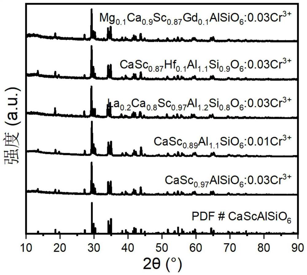
[0048] The chemical composition formula of the near-infrared fluorescent powder of this embodiment is Cr x CaS 1-x AlSiO 6 , where x=0.03. According to the stoichiometric ratio of each element in the chemical formula, accurately weigh Li 2 CO 3 ,CaCO 3 ,Sc 2 o 3 ,Al 2 o 3 , SiO 2 ,Cr 2 o 3 High-purity powder raw materials are placed in an agate mortar and ground for about 30 minutes to fully mix the raw materials evenly. Transfer the mixed raw materials to an alumina crucible, cover and place in 20% H 2 +80%N 2 Sinter at 1500°C for 8 hours in an atmosphere high-temperature reaction furnace, take it out after natural cooling, and grind again for about 10 minutes to obtain Cr 0.03 CaS 0.97 AlSiO 6 Phosphor powder, its XRD and fluorescence spectra are as follows image 3 and Figure 4 shown, from image 3 It can be seen that the phosphor is a single phase, from Figure 4 It can be seen that the phosphor can perfectly match the 460nm blue light chip, and emit n...

Embodiment 2-20

[0052] The chemical composition formula, calcination temperature, time and grinding time of Examples 2-20 are shown in Table 1; refer to Example 1 for the preparation method.

[0053] The XRD of the near-infrared fluorescent material prepared in Examples 1, 8, 12, 14 and 16 and the comparison chart of the standard card are shown in image 3 , it can be seen from the figure that the prepared phosphor is a single phase, and the phosphor obtained in other embodiments is also a single phase;

Embodiment 2

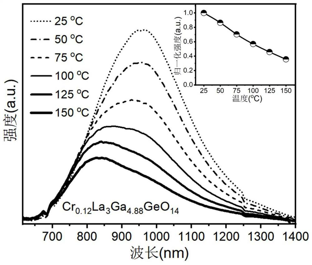
[0054] The Cr prepared by embodiment 2 0.01 CaS 0.84 al 1.15 SiO 6 The fluorescence thermal stability test chart of Figure 5 , it can be seen from the figure that the stability of the phosphor is good, and the luminous intensity at 100°C and 150°C is 69% and 44% of that at room temperature, respectively;


PUM

PropertyMeasurementUnit
emission peakaaaaaaaaaa
full width at half maximumaaaaaaaaaa
emission peakaaaaaaaaaa

Abstract

The invention discloses an oxide near-infrared light-emitting material, a preparation method thereof and a light-emitting device. The near-infrared light-emitting material comprises an inorganic compound, wherein the chemical formula of the inorganic compound is AxByCzOqDp; wherein A is one or a combination of more than two of elements of Mg, Ca, Sr, Ba, Lu, Y, Gd or La; B is one or a combination of more than two of Sc, In, Ga, Mg, Zr, Ti, Hf, Sn, Lu, Y, Gd or La; C is one or a combination of more than two of Al, Si or Ge elements; O is an oxygen element; D is a Cr element; 0.7 < = x < = 1.3, 0.7 < = y < = 1.3, 1 < = Z < = 3, 5 < = q < = 7, and 0 < p < = 0.3. The emission peak wavelength of the near-infrared light-emitting material is about 930 nm, the half-peak width is about 210 nm, the near-infrared light-emitting material can be efficiently excited by blue light, and the chemical stability and the thermal stability are good.

Description

technical field [0001] The invention belongs to the technical field of luminescent materials, and in particular relates to an oxide near-infrared luminescent material, a preparation method thereof, and a luminescent device. Background technique [0002] In recent years, near-infrared light has shown great application prospects in the fields of night vision lighting, security and security, remote sensing, optical fiber communication, plant growth, non-destructive testing, targeted therapy, iris recognition, and food composition analysis. Infrared light sources are still far from meeting the actual needs in terms of luminous efficiency and emission bandwidth, so the development of new broadband near-infrared light sources has become a research hotspot of scholars at home and abroad. Among many design schemes, the near-infrared phosphor-converted LED has excellent emission peak position, spectral band width, luminous efficiency and thermal stability, and has a simple structure,...

Claims


Application Information

Patent Timeline
Patent Type & Authority Applications(China)
IPC IPC(8): C09K11/80H01L33/50
CPCC09K11/77062H01L33/504Y02P60/14
Inventor 夏志国刘高超
Owner SOUTH CHINA UNIV OF TECH
Why Eureka
Try Eureka