Coal-fired boiler with low carbon dioxide emission and combustion method

A low carbon dioxide, coal-fired boiler technology, applied in the field of boiler combustion, can solve the problems of large emission of pollutants, high post-processing cost, large processing load, etc. load effect

Active Publication Date: 2021-12-28
内蒙古靓固科技有限责任公司
View PDF6 Cites 0 Cited by
  • Summary
  • Abstract
  • Description
  • Claims
  • Application Information

AI Technical Summary

Problems solved by technology

[0005] The object of the present invention is to provide a coal-fired boiler and a combustion method with low carbon dioxide emission, which uses the air supply pipe in the top sunken air supply area to continuously inject airflow to the center of the furnace, and the airflow and the smoke and carbon dioxide in the ascending channel are hedged to form a wind. Screen, blocking smoke, CO 2 , SO 2 , NO X Wait for the discharge to go up, and then pass through the windless area in the center of the furnace to return to the combustion layer and mix with coal to form a secondary cycle combustion, which solves the high coal cost caused by insufficient coal combustion in the prior art and is discharged from the boiler , and the high post-processing cost and heavy processing load caused by the large amount of carbon dioxide, smoke and other pollutant emissions

Method used


Image

  • Coal-fired boiler with low carbon dioxide emission and combustion method
  • Coal-fired boiler with low carbon dioxide emission and combustion method
  • Coal-fired boiler with low carbon dioxide emission and combustion method

Examples


Embodiment 1

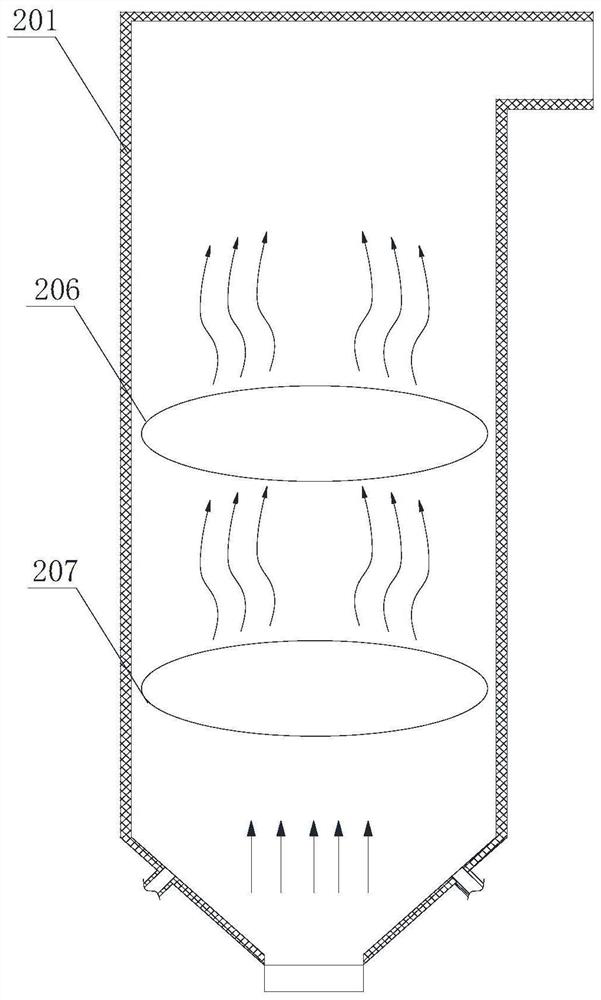
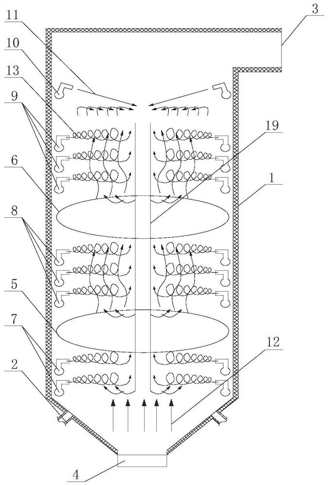
[0057] Such as Figure 3 to Figure 5 The shown coal-fired boiler with low carbon dioxide emissions includes a furnace body 1, and the furnace body 1 is provided with a bottom air inlet 2, an air exhaust port 3, a combustion air supply area 5 and a burnout air supply area 6, so that The diagonal air inlets 14 of the combustion air supply area 5 and the burnout air supply area 6 supply air to the furnace body 1 to form a tangential wind field, and also include a sunken air supply area above the burnout air supply area 6 10. The sunken air supply area 10 is used to inject a downdraft airflow 11 to the center of the furnace body 1, and the downdraft airflow 11 passes through the central windless area 17 of the tangential wind field and sinks to the bottom and the bottom of the boiler Updraft 12 mixing.

[0058] In some embodiments, such as Figure 4 As shown, the sunken air supply area 10 includes a first air supply pipe 15 installed on the inner wall of the furnace body 1, the ...

Embodiment 2

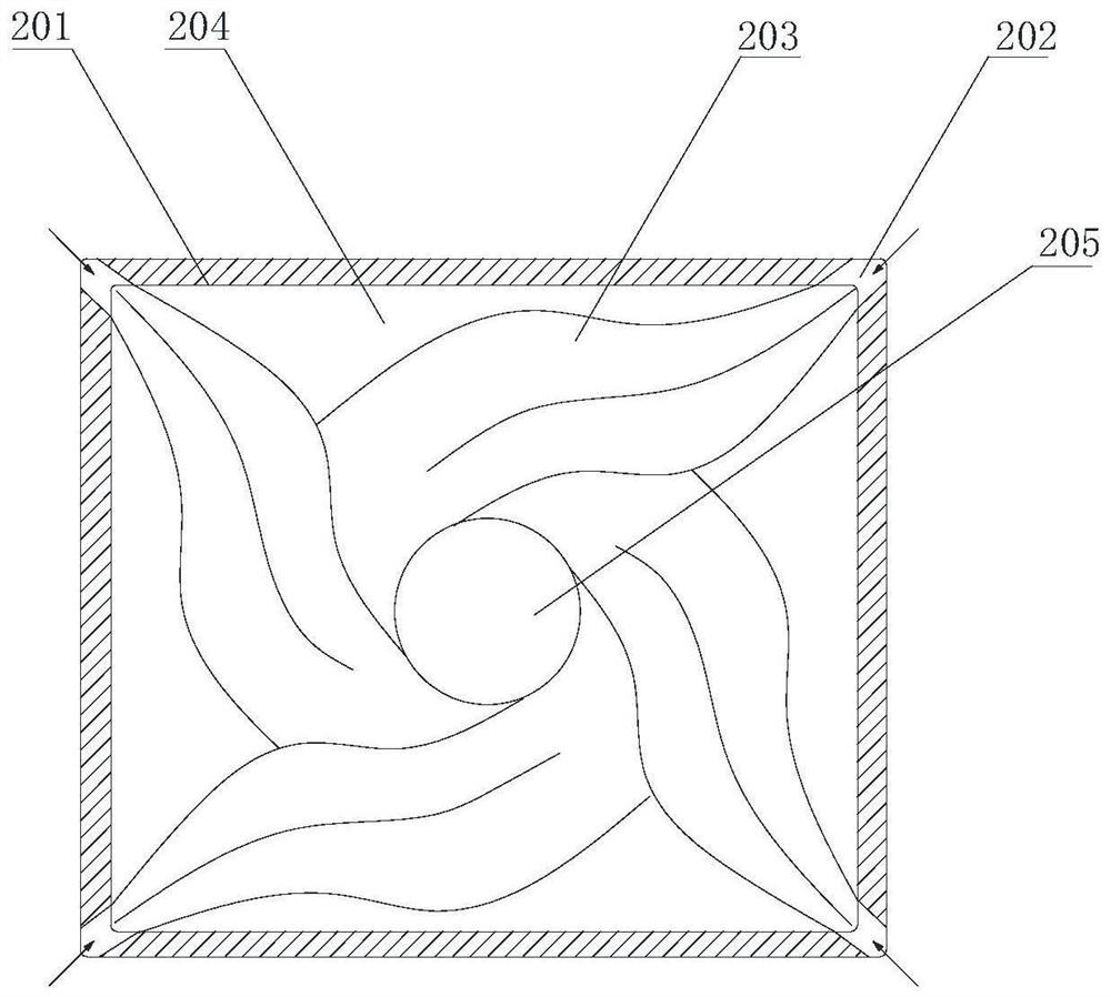
[0064] On the basis of Example 1, such as image 3 As shown, the furnace body 1 is also provided with a lower air supply area 7 and a middle air supply area 8, the lower air supply area 7 is located below the combustion air supply area 5, and the middle air supply area 8 is located at Between the combustion air supply area 5 and the burnout air supply area 6, the lower air supply area 7 includes two sets of air supply assemblies, and the middle air supply area 8 includes three sets of air supply assemblies, such as Figure 5 As shown, the air supply assembly includes diagonal air inlets 14, which are used to supply air into the furnace body 1 to form a tangential wind field, and two adjacent diagonal air inlets 14 are arranged between There is a second air supply pipe 16, and the second air supply pipe 16 is used to distribute air to the tangential wind field; the air supply volume of the central air supply area 8 is 25% to 35% of the total air volume entering the furnace body...

Embodiment 3

[0072] Such as Figure 7 to Figure 9As shown, on the basis of the above-mentioned embodiments, the nozzle 18 is detachably connected to the air outlet 163 of the first air supply pipe 15 and the second air supply pipe 16, and the nozzle 18 includes a nozzle body 181. The nozzle main body 181 is provided with a helical groove 182 extending helically along the inner wall of the nozzle main body 181. The nozzle main body 181 is provided with a partition 185, and the partition 185 divides the inner space of the nozzle main body 181 into an air inlet connected to the inlet port. area and the cyclone area connected to the gas outlet, the partition 185 is provided with a chamfered hole 186 connecting the inlet area and the cyclone area, the central axis of the chamfered hole 186 has an included angle with the central axis of the partition 185, and the nozzle The main body 181 is also provided with at least one swirl-assisting tube 184, the inside of which swirl-assisting tube 184 for...


PUM


Abstract

The invention relates to a coal-fired boiler with low carbon dioxide emission and a combustion method. The boiler comprises a boiler body, wherein a bottom air inlet, an air outlet, a combustion air supply area and a burnout air supply area are formed in the boiler body; diagonal air inlets of the combustion air supply area and the burnout air supply area supply air to the boiler body to form a tangent circle air field; the boiler further comprises a sinking air supply area located above the burnout air supply area; the sinking air supply area is used for spraying sinking airflow to the center of the boiler body; and the sinking airflow penetrates through a central air-free area of the tangent circle air field to sink to the bottom of the boiler to be mixed with bottom ascending airflow. The sinking airflow generated by the boiler achieves blocking above the burnout air supply area, meanwhile, the sinking airflow sinks from the central air-free area and is combined with the bottom ascending airflow to form circulating airflow, so that the contact time of emissions, coal and oxygen is prolonged, the reaction of all substances is more sufficient, the burnout rate of fuel is obviously increased, the coal combustion cost is reduced, solid particle impurities in smoke dust are reduced, and the emission of gas emissions of CO2, SO2 and NOX is reduced.

Description

technical field [0001] The invention relates to the technical field of boiler combustion, in particular to a coal-fired boiler and a combustion method capable of reducing emissions of smoke, carbon dioxide and other emissions. Background technique [0002] With the rapid development of the national economy, my country's energy consumption is increasing day by day, and China has become the world's largest energy consumer. In my country's total primary energy consumption, coal consumption has an absolute advantage, accounting for about 70% of total energy consumption. [0003] As an important energy source, coal plays an important role in our country, but at the same time, coal burning also causes serious pollution to the environment. Carbon dioxide and nitrogen oxides are a class of gases that can cause serious air pollution, and are basically considered to be one of the main sources of air pollution. At present, the most important feature of my country's energy composition...

Claims


Application Information

Patent Timeline
Patent Type & Authority Applications(China)
IPC IPC(8): F23C7/02F23C7/00F23C9/06
CPCF23C7/02F23C7/002F23C9/06F23C2900/06041Y02E20/34
Inventor 李谦李秋实罗业富任耕北
Owner 内蒙古靓固科技有限责任公司
Why Eureka
Try Eureka