Ideal diode

An ideal diode and triode technology, applied in pulse processing, logic circuit coupling/interface using field effect transistors, conversion equipment without intermediate conversion to AC, etc. Advanced problems, to achieve the effect of low design difficulty and cost, lower power consumption, and lower power consumption

Pending Publication Date: 2022-03-22
SUZHOU KAIWEITE SEMICON
View PDF0 Cites 0 Cited by
  • Summary
  • Abstract
  • Description
  • Claims
  • Application Information

AI Technical Summary

Problems solved by technology

However, for a small load solution, it is not suitable to use N_MOSFET as an ideal diode. First, the cost of the solution is relatively high, and second, the design of the control IC is relatively difficult.

Method used


Image

  • Ideal diode
  • Ideal diode
  • Ideal diode

Examples


Embodiment

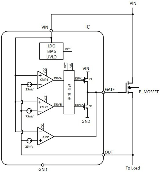
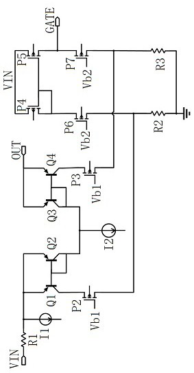
[0020] Example: such as figure 2 As shown, an ideal diode, the diode includes a control IC chip and a PMOS tube, the control IC chip is connected to the PMOS tube, and the control IC chip includes a power bias enabling module, a low-voltage power supply VCC module inside the chip, and a first The comparator CMP1, the second comparator CMP2, the level shifting module, the operational amplifier AMP, the power supply pin VIN of the control IC chip is connected to the source end of the PMOS tube, the GATE pin of the control IC chip is connected to the gate end of the PMOS tube, The OUT pin of the control IC chip is connected to the drain end of the PMOS tube. The operational amplifier AMP includes the first set of current mirrors composed of transistors Q1 and Q2, the second set of current mirrors composed of transistors Q3 and Q4, and the PMOS transistor P4 , the first output branch composed of PMOS transistor P6 and resistor R2 and the second output branch composed of PMOS tran...


PUM


Abstract

An ideal diode disclosed by the present invention comprises a control IC chip and a PMOS tube, the control IC chip internally comprises a power supply bias enabling module, a chip internal low-voltage power supply VCC module, a first comparator CMP1, a second comparator CMP2, a level conversion module and an operational amplifier AMP, and the operational amplifier AMP comprises a first group of current mirrors composed of a triode Q1 and a triode Q2. The first group of current mirrors comprises a triode Q3 and a triode Q4, the second group of current mirrors comprise a triode Q3 and a triode Q4, the first output branch comprises a PMOS tube P4, a PMOS tube P6 and a resistor R2, the second output branch comprises a PMOS tube P5, a PMOS tube P7 and a resistor R3, and the output end of the operational amplifier AMP is connected with the grid end of the PMOS tube. The design of a charge pump in the control IC chip is omitted, and the whole size is extremely simplified.

Description

technical field [0001] The invention belongs to the technical field of semiconductors, and in particular relates to an ideal diode. Background technique [0002] With the development of semiconductor material technology, the conduction voltage drop of traditional diodes is getting lower and lower. The conduction voltage drop of silicon-based diodes is about 0.7V, and when the conduction current increases, the conduction voltage drop can reach 1V; the conduction voltage drop of Schottky diodes is about 0.4V, and when the conduction current increases , the conduction voltage drop can reach 0.8V; the germanium-based diode conduction voltage drop is about 0.3V, and it can reach 0.4V when the conduction current increases. In the application, the corresponding diode can be selected according to the demand, so as to reduce the power loss on the diode. However, with the increase of the load capacity of the power system, for example, the load current is 3A, even the germanium-based...

Claims


Application Information

Patent Timeline
IPC IPC(8): H02M1/08H02M3/07H03K5/24H03K19/0185
CPCH02M1/08H02M3/07H03K5/2472H03K19/018507
Inventor 涂才根张胜谭在超罗寅丁国华
Owner SUZHOU KAIWEITE SEMICON
Why Eureka
Try Eureka