Laminated organic light-emitting device

An electroluminescent device and electroluminescent technology, applied in the fields of electro-solid devices, organic chemistry, luminescent materials, etc., to achieve the effect of improving device performance, improving device performance, and increasing device stability

Pending Publication Date: 2022-08-02
BEIJING SUMMER SPROUT TECH CO LTD
View PDF4 Cites 1 Cited by
  • Summary
  • Abstract
  • Description
  • Claims
  • Application Information

AI Technical Summary

Problems solved by technology

[0007] However, there is no public report of a stacked device that combines deep LUMO energy level materials with deep HOMO energy level materials as a hole

Method used


Image

  • Laminated organic light-emitting device
  • Laminated organic light-emitting device
  • Laminated organic light-emitting device

Examples


Embodiment 1-1

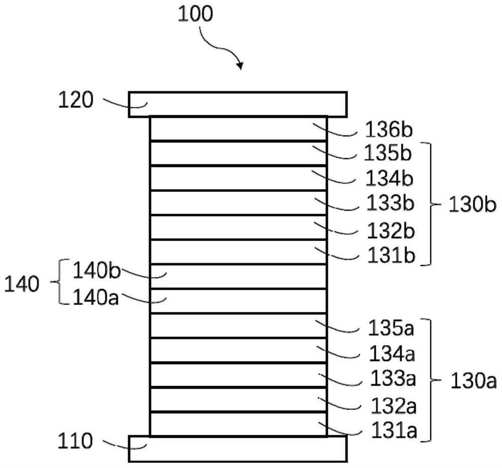
[0201] Example 1-1: Preparation of two-layer red light stacked organic electroluminescence device 100, such as figure 1 shown.

[0202] First, using a 0.7 mm thick glass substrate with a pre-patterned 120 nm thick indium tin oxide (ITO) anode 110, the ITO surface was subjected to oxygen plasma and UV ozone after washing the substrate with deionized water and detergent. deal with. Subsequently, the substrates were dried in a glove box to remove moisture and loaded onto a rack into a vacuum chamber. The organic layer specified below, at a vacuum of approximately 10 -6 In the case of Torr, the evaporation was sequentially performed on the ITO anode layer by vacuum thermal evaporation at a rate of 0.1-10 Å / sec. First, the first light-emitting unit 130a is vapor-deposited, including: simultaneously vapor-depositing compound H-124 and compound 1-70 as the hole injection layer 131a (HIL, weight ratio 97:3, ), the vapor-deposited compound H-124 was used as the hole transport laye...

Embodiment 2-1

[0217] Example 2-1: Preparation of another red light stacked organic electroluminescent device. The preparation method is the same as that of Example 1-1, except: 1) In the first light-emitting unit, the following hole injection layer is used instead of the hole injection layer of the first light-emitting unit in Example 1-1, and the following holes are used A transport layer to replace the hole transport layer of the first light-emitting unit in Example 1-1: Compound H-176 and Compound 1-70 were simultaneously evaporated as a hole injection layer (HIL, weight ratio 97:3, ), the evaporation compound H-176 was used as a hole transport layer (HTL, ); 2) In the second light-emitting unit, the following hole injection layer was used to replace the hole injection layer of the second light-emitting unit in Example 1-1, and the following hole transport layer was used to replace the hole injection layer of Example 1-1. Hole transport layer of two light-emitting units: Compound H-17...

Embodiment 3-1

[0228] Example 3-1: Preparation of another red light stacked organic electroluminescent device. The preparation method is the same as that of Example 1-1, except: 1) In the first light-emitting unit, the following hole injection layer is used instead of the hole injection layer of the first light-emitting unit in Example 1-1, and the following holes are used A transport layer to replace the hole transport layer of the first light-emitting unit in Example 1-1: Compound H-176 and Compound 1-70 were simultaneously evaporated as a hole injection layer (HIL, weight ratio 97:3, ), the evaporation compound H-176 was used as a hole transport layer (HTL, ); 2) In the second light-emitting unit, the following hole injection layer was used to replace the hole injection layer of the second light-emitting unit in Example 1-1, and the following hole transport layer was used to replace the hole injection layer of Example 1-1. Hole transport layer of two light-emitting units: Compound H-17...


PUM


Abstract

Disclosed is a laminated organic electroluminescent device. The laminated organic light-emitting device comprises a first electrode, a second electrode and at least two light-emitting units arranged between the first electrode and the second electrode, wherein each light-emitting unit comprises at least one light-emitting layer; wherein at least one light-emitting unit comprises a first organic layer, and the first organic layer comprises a first organic material and a second organic material; wherein a charge generation layer is arranged between at least one group of adjacent two light-emitting units, the charge generation layer comprises a buffer layer, and the buffer layer comprises a third organic material; wherein the LUMO energy level value of the first organic material is greater than or equal to the LUMO energy level value of the third organic material, and the LUMO energy level value of the third organic material is greater than 4.90 eV; wherein the HOMO energy level value of the second organic material is greater than 4.99 eV. The device can provide better device performance and a more simplified manufacturing process. The invention further discloses a display assembly comprising the device.

Description

technical field [0001] The present invention relates to a stacked organic electroluminescence device, which comprises two or more light-emitting units, and a charge generating layer is arranged between adjacent light-emitting units. More particularly, it relates to an organic electroluminescent device having an organic layer doped with a p-type material and a display assembly comprising the organic electroluminescent device. Background technique [0002] An organic electroluminescent device (OLED) is composed of a cathode, an anode, and an organic light-emitting material between the cathode and the anode. By applying a voltage across the cathode and anode of the device, electrical energy is converted into light, with wide-angle, high contrast and Advantages such as faster response time. Tang and Van Slyke of Eastman Kodak reported an organic light-emitting device in 1987 with an arylamine hole transport layer and a tris-8-hydroxyquinoline-aluminum layer as the electron tran...

Claims


Application Information

Patent Timeline
IPC IPC(8): H01L51/50
CPCH10K50/11H10K2101/40H10K50/13C09K11/06C07D498/04C07D263/32C07D513/04C07D517/04C07D213/61C07D213/84C07D239/30C07D239/26C07D239/28C07D251/20C07D251/24C07D413/14C07D417/14C07D263/34C07D263/40C07D263/46C07D277/22C07D277/24C07D277/26C07D277/30C07D277/32C07D277/34C07D277/36C07D277/56C07D209/86C07D403/12C07D401/12C07D405/12C07D409/12C07D209/56C07D401/04C07D405/04C07D409/04C07D403/14H10K85/631H10K85/656H10K85/657H10K85/6572H10K50/15H10K50/17H10K50/19H10K71/30H10K85/626H10K85/649H10K85/633H10K85/654H10K85/6574H10K85/6576H10K50/80H10K50/156H10K85/622H10K85/653
Inventor 王静庞惠卿崔至皓邝志远夏传军
Owner BEIJING SUMMER SPROUT TECH CO LTD
Why Eureka
Try Eureka