Microwave flue gas desulfurization and denitration method and apparatus
A technology for desulfurization, denitrification, and microwave devices, which is applied in separation methods, chemical instruments and methods, and dispersed particle separation, can solve problems such as reactor corrosion and insufficient use of energy, and achieve low operating costs, reduced losses, and reduced corrosion. sexual effect
- Summary
- Abstract
- Description
- Claims
- Application Information
AI Technical Summary
Problems solved by technology
Method used
Image
Examples
Embodiment 1
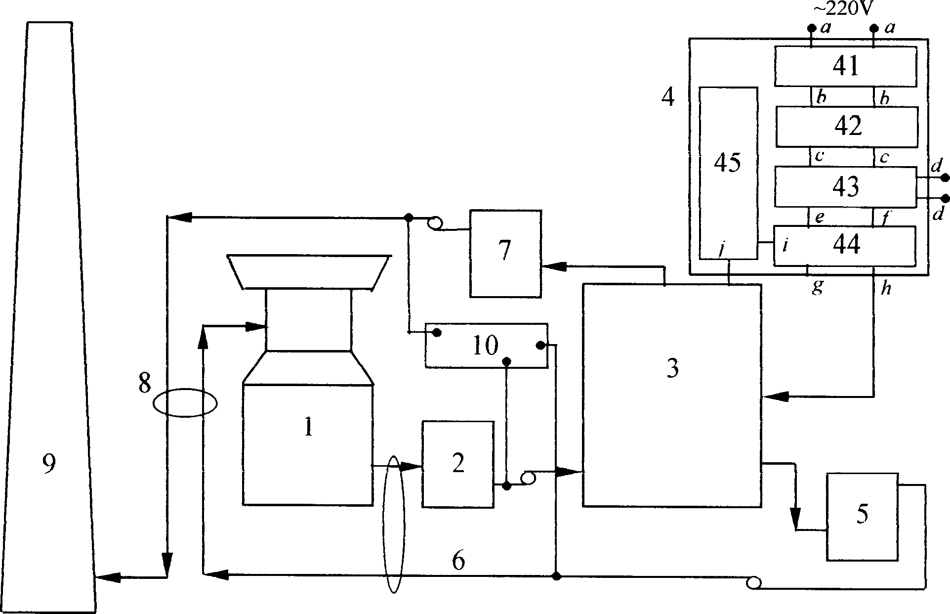
[0035] Figure 1 is A schematic process flow diagram of Embodiment 1 of the present invention.
[0036] Figure 1, the coal-fired flue gas from the combustion furnace (1), after most of the solid particles are sucked by the electrostatic vacuum cleaner (2), is compressed into the reactor (3) through the compressor, and at the same time, the power measuring instrument ( 45) The microwave energy after measuring and adjusting the peak power, pulse width, and duty ratio also enters the reactor (3), and the reactor (3) is equipped with an adsorption sensitizer, which is Ni, FeO or MnO 2 Spherical or cylindrical particles of nanomaterials, etc., are used as adsorption sensitizers, whose function is to focus microwave energy onto the surface of the adsorbent, and reach a high temperature of more than 1000 degrees at several sensitive points on the surface of the adsorbent, so that the microwave device ( 4) Most of the energy (about 80%) entering the reactor (3) is concentrated on th...
Embodiment 2
[0057] The microwave device used in embodiment 2 is the same as that in embodiment 1. Embodiment 2 is characterized in that the adsorption sensitizer reaction layer is not provided in the reactor (3), and instead, NH is passed into the reactor (3). 3 Gas and water vapor react to form reaction products. The remaining steps of the microwave flue gas desulfurization and denitrification method are the same as
[0058] Example 1,
[0059] Figure 6 isA schematic process flow diagram of Embodiment 2 of the present invention.
[0060] Figure 6 , combustion furnace (1), dust collector (2), humidification tower (27), water vapor (28), ammonia addition system (29), gas compressor, reactor (3), collector (5), gas compressor , the combustion furnace (1) is connected in series through pipelines, and the reactor (3), collector (7), gas compressor, and flue (9) are connected in sequence by pipelines, and the water vapor (28) provides water vapor to the humidifying tower (27) , Ammonif...
PUM
 Abstract
Description
Claims
Application Information
 - R&D
- Intellectual Property
- Life Sciences
- Materials
- Tech Scout
- Unparalleled Data Quality
- Higher Quality Content
- 60% Fewer Hallucinations
Browse by: Latest US Patents, China's latest patents, Technical Efficacy Thesaurus, Application Domain, Technology Topic, Popular Technical Reports.
© 2025 PatSnap. All rights reserved.Legal|Privacy policy|Modern Slavery Act Transparency Statement|Sitemap|About US| Contact US: help@patsnap.com


