Tunnel effect magneto-resistance device and preparing method

A technology of tunnel effect and magnetoresistance, which is applied in the manufacture/processing of magnetic field controlled resistors and electromagnetic devices, which can solve the problems that the junction resistance cannot return to the initial value, the junction resistance is complex and difficult, etc., and achieve the improvement of magnetic field response characteristics and stability, the preparation method is simple, and the effect of improving the coercive force

Inactive Publication Date: 2003-11-26
INST OF PHYSICS - CHINESE ACAD OF SCI
View PDF1 Cites 6 Cited by
  • Summary
  • Abstract
  • Description
  • Claims
  • Application Information

AI Technical Summary

Problems solved by technology

In the above technology, the two electrode layers are designed into different shapes and sizes, and the coercivity of the two electrode layers is adjusted by using shape anisotropy, but there are still difficulties in obtaining ideal spin states in the tunnel junction.
The main disadvantage of this device is that the junction resistance exhibits complex changes under a magnetic field, so that it is impossible to predict whether the junction resistance is in a high-resistance state or a low-resistance state under a certain magnetic signal.
And the stability of the device is poor, after the magnetic signal is applied, the junction resistance cannot return to the initial value
Its usefulness is limited by the difficulty of operating the device in a stable, repeatable state

Method used


Image

  • Tunnel effect magneto-resistance device and preparing method
  • Tunnel effect magneto-resistance device and preparing method
  • Tunnel effect magneto-resistance device and preparing method

Examples


Embodiment 1

[0032] The present invention must use the following equipment and materials:

[0033] Equipment requirements:

[0034] -Ultrasonic cleaner (the index does not make special requirements);

[0035] -Magnetron sputtering vacuum coating equipment: the ultimate vacuum is 5.0′10-4Pa, the maximum heating temperature of the substrate stage is 1000°C, and the target-base distance is 4.0-4.5cm;

[0036] -Supporting vacuum pump unit for magnetron sputtering vacuum coating equipment:

[0037] The first stage vacuum pump: mechanical pump is adopted, the pumping rate is 8L / s, and the ultimate pressure is 6′10-2Pa;

[0038] The second-stage vacuum pump: molecular pump is adopted, the pumping rate is 600L / s, and the ultimate pressure is 1′10-8Pa;

[0039] -Supporting temperature controller for magnetron sputtering vacuum plating equipment: 818 single-loop process regulator produced by Oulu Company;

[0040] -Ion etching equipment: LKJ-1C-150 ion etching instrument of the 23rd Institute of C...

Embodiment 2

[0063] After completing the preparation steps 1-6 in Example 1, the further preparation steps are as follows:

[0064] 7a. Using the same process as step 1, and using a glass-based mask to prepare a photoresist mask on the surface of the multilayer film;

[0065] 8a. Deposit a layer of Ag on the surface of the multilayer film by using a magnetron sputtering device and in a DC sputtering mode;

[0066] 9a. Immersed in acetone, while removing the photoresist, the noble metal layer above the photoresist is also removed, and the remaining part of the noble metal layer forms a contact electrode;

[0067] 10a. Using indium as solder, solder the conductive leads on the bottom electrode layer and the top electrode layer of the tunnel junction.

Embodiment 3

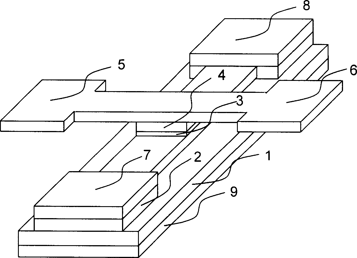
[0069] The tunnel effect magnetoresistance prepared by each step in embodiment 1 or 2 is as follows figure 1 shown. Multilayer films on SrTiO 3 , MgO, Al 2 o 3 or Si wafers as epitaxial growth on the substrate 9, including La with a thickness of 30 or 80nm 0.33 Ca 0.67 MnO 3 Pinning layer 1, La with a thickness of 20 or 100 nm 0.67 Ca 0.33 MnO 3 Bottom electrode layer 2, barrier layer 3 with a thickness of 1 or 8 nm, La with a thickness of 20 or 80 nm 0.67 Ca 0.33 MnO 3 Top electrode layer 4. The barrier layer 3 is located above the bottom electrode layer 2 and below the top electrode layer 4; the antiferromagnetic perovskite manganese oxide compound on the substrate 9 is the pinning layer 1, and the pinning layer 1 is located at the bottom electrode Below layer 2; the bottom electrode layer is strip-shaped, with lead terminals at both ends; above the bottom electrode layer 2 is a square barrier layer 3 and top electrode layer 4, and the top of the top electrode la...


PUM


Abstract

A tunnel-effect magnetic resistor includes a substrate with a bottom electrode layer, a potential barrier layer and a top electrode layer, the potential barrier layer is above the bottom electrode layer but under the top electrode layer, a nailer layer of anti-ferromagnetism perovskite Mn oxide above the substrate and under the strip-shape bottom electrode with lead outlet terminal at both ends, the square potential barrier layer and the top electrode layer above it with lead outlet terminal at the SiO2 seal around them, one or two leads are led out from the outlet terminals of the bottom andthe top electrode layers. With the help of tunnel effect, the current expresses a magnetic resistance effect and the resistance variation, rate of the tunnel junction reaches 28% within 600 Oe magnetic field range.

Description

technical field [0001] The invention belongs to a magnetic sensor and a memory, in particular to a tunnel effect magnetoresistance device and a preparation method. Background technique [0002] The magnetoresistance effect has a very important application prospect in magnetic recording and storage. In recent years, people have developed a strong interest in this field. Divided from the generation mechanism, the magnetoresistance effect can be divided into many kinds, but the applications that attract people's attention mainly include giant magnetoresistance (hereinafter referred to as GMR) in metal multilayer films, metal-based spin valves and metal- Tunneling magnetoresistance (hereafter referred to simply as TMR) in an insulator-metal junction. In applications as magnetic sensors and memory, the main purpose of the research is to improve the magnetic field sensitivity of the device, that is, for a certain magnitude of magnetic signal, the magneto...

Claims


Application Information

Patent Timeline
Patent Type & Authority Applications(China)
IPC IPC(8): H01L43/08H01L43/12
Inventor 赵柏儒蔡纯龚伟志许波张福昌
Owner INST OF PHYSICS - CHINESE ACAD OF SCI
Why Eureka
Try Eureka