Railway signal cable and method for manufacturing the same

A railway signal and manufacturing method technology, applied in the direction of cable/conductor manufacturing, communication cables, insulated cables, etc., can solve the problems of dielectric constant reduction, line transmission attenuation constant reduction, and affecting signal transmission quality, etc., to save construction costs, The effect of protecting product quality and reasonable workmanship

Inactive Publication Date: 2004-01-14
JIANGSU DONGQIANG
View PDF0 Cites 10 Cited by
  • Summary
  • Abstract
  • Description
  • Claims
  • Application Information

AI Technical Summary

Problems solved by technology

"Modern Wired Transmission", No. 1, 1996, "Development of Physically Foamed Skin/Foam/Sheath Insulated Local Communication Cable (HYPA)" introduces a cable core wire insulation layer structure that has been applied to railway digital signal cables , because the insulating layer of the core wire structure has many dense and disconnected foam layers in the middle of the core and the outer skin, its dielectric constant is much lower than that of the solid-skin insulating layer, so that the line transmission The attenuation constant is greatly reduced. Therefore, this kind of leather/foam/skin railway signal cable h

Method used


Image

  • Railway signal cable and method for manufacturing the same
  • Railway signal cable and method for manufacturing the same
  • Railway signal cable and method for manufacturing the same

Examples


Embodiment 1

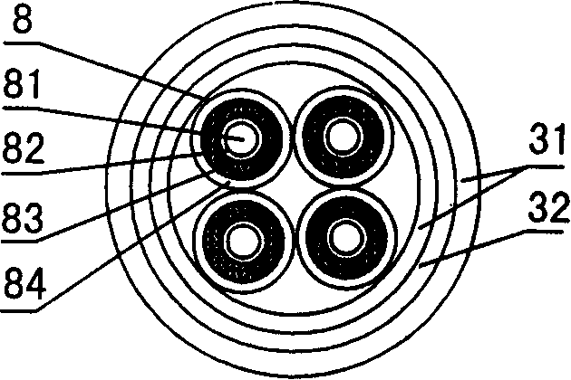
[0026] First, a copper conductor with a circular cross-section and a diameter of 1.0mm is drawn by a wire drawing machine; and the conductor is fed into an insulating layer extruder with a three-layer co-extrusion function, and the extruder heats and melts the three layers of insulating materials And form a three-layer insulating layer of solid inner skin, foam and solid outer skin outside the conductor. In the process of heating and extrusion, injecting nitrogen into the foam layer raw material means adopting the general physical foaming method, or adding azo to the foam layer raw material. Diisobutyronitrile (N-type foaming agent), azodicarbonyl ester (AC-type foaming agent) and other foaming agents are extruded and foamed, that is, the chemical foaming method is used; the insulating layer material is made of polyethylene or polyester. Polyolefin materials such as propylene; add color masterbatches of various colors to the polyolefin material of the solid skin layer as needed...

Embodiment 2

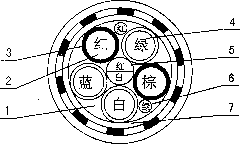
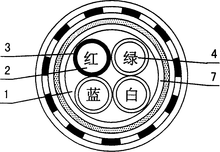
[0028] The copper wire is drawn into a copper conductor with a diameter of 1.13mm and a circular section, and the copper conductor is sent to three insulation layer extruders in sequence to complete the extrusion of the solid inner skin layer, the extrusion of the middle foam layer and the solid Extrusion of the outer skin layer, adding a chemical foaming agent to the raw material of the middle extruder to form the middle foam layer, and then wind-cooling and water-cooling the insulated core wires into a coil, twisting the coiled insulated core wires into a star-shaped quad Wire group and wire pair group; cover the pre-prepared shielding tape with the shielding tape on the four-wire group of the specified color, and wrap the other four-wire groups without shielding layer with wrapping tape and form a coil, and then shield the four-wire group, The four-wire group, pair-wire group, and core wires are twisted into cables according to the design requirements, and the following proc...

Embodiment 3

[0030] After being cabled according to embodiment 1, complete following operation successively again, the plastic insulation layer integrated sheath, steel tape armoring, outer sheath are installed additional.


PUM


Abstract

The present invention discloses a railway signal cable and a manufacturing method thereof. The railway signal cable includes a outer protective layer, a cable core and line sets and core wires in the cable core, in which the insulation layers of the core wires have structure as skin-foam-skin, at least one of the line sets includes four lines with a shielding layer, and the other do not include the shielding layer. The manufacturing method includes: manufacturing the shielding layers for the line sets, and wrapping the shielding layers out of the shielding line sets, etc.

Description

technical field [0001] The invention relates to a railway cable, especially a railway signal cable with good high-frequency signal and low-frequency signal transmission compatibility and a manufacturing method thereof. Background technique [0002] Most of the existing railway signal cables are constructed of an outer protective layer and a cable core inside the outer protective layer. The cable core is composed of core wires divided into several wire groups. The outer insulating layer of the core wire conductor adopts a single-layer insulating layer. The layer is a solid layer structure, which has a relatively high dielectric constant, which directly affects the anti-attenuation performance of the cable, especially when the cable transmits high-frequency signals. "Modern Wired Transmission", No. 1, 1996, "Development of Physically Foamed Skin / Foam / Sheath Insulated Local Communication Cable (HYPA)" introduces a cable core insulation layer structure that has been applied to r...

Claims


Application Information

Patent Timeline
IPC IPC(8): H01B7/02H01B11/00H01B11/06H01B13/00
Inventor 王子纯姚勰陈子洪
Owner JIANGSU DONGQIANG
Why Eureka
Try Eureka