Residual polymer eliminating method

A technology of polymers and mixed gases, which is applied in the fields of electrical components, semiconductor/solid-state device manufacturing, circuits, etc., can solve problems such as inability to remove, and achieve the effects of deleting removal steps and time, stabilizing product output, and shortening product output stability

Inactive Publication Date: 2004-01-21
UNITED MICROELECTRONICS CORP
View PDF0 Cites 24 Cited by
  • Summary
  • Abstract
  • Description
  • Claims
  • Application Information

AI Technical Summary

Problems solved by technology

However, after performing the polymer removal process by the conventional method, it is still possible to observe polymer residues on the substrate through an electron microscope, and these hardened polymers (harden polymer) seem to be repeatedly cleaned with a solvent (solvent) The wet cleaning (WetClean) can not remove

Method used


Image

  • Residual polymer eliminating method
  • Residual polymer eliminating method
  • Residual polymer eliminating method

Examples


no. 1 example

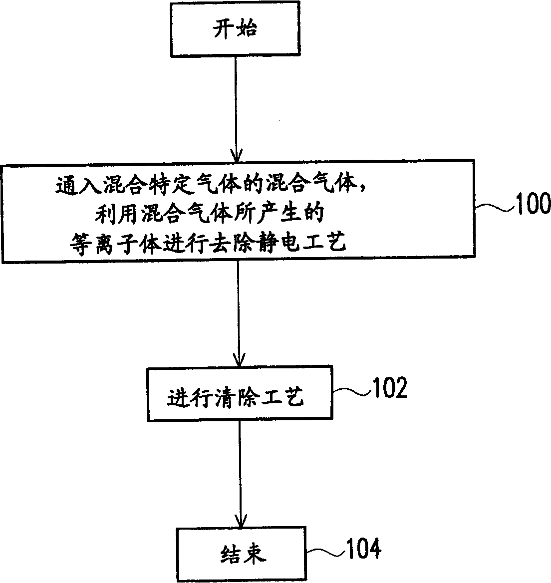
[0027] figure 1 It is a flow chart of steps for removing residual polymers according to a preferred embodiment of the present invention, which can be applied to an etching process for forming openings in a dielectric layer, wherein the dielectric layer is, for example, a silicon oxide dielectric layer, and the dielectric layer is The openings formed in are, for example, Metal Via (MVIA) openings, Contact openings, and Dual Damascene openings. Moreover, this embodiment adopts a magnetic-enhanced reactive ion etching (Magnetic-Enhanced RIE, MERIE for short) system machine.

[0028] Usually, the reaction gas used for etching is a gas containing carbon fluoride, such as tetracarbon octafluoride (C 4 f 8 ), five carbon octafluoride (C 5 f 8 ) or tetracarbon hexafluoride (C 4 f 6 ). Because after the etching process is carried out on the machine of the magnetic field enhanced reactive ion etching system, it is easy to have the problem of uneven accumulation of electrons due t...

no. 2 example

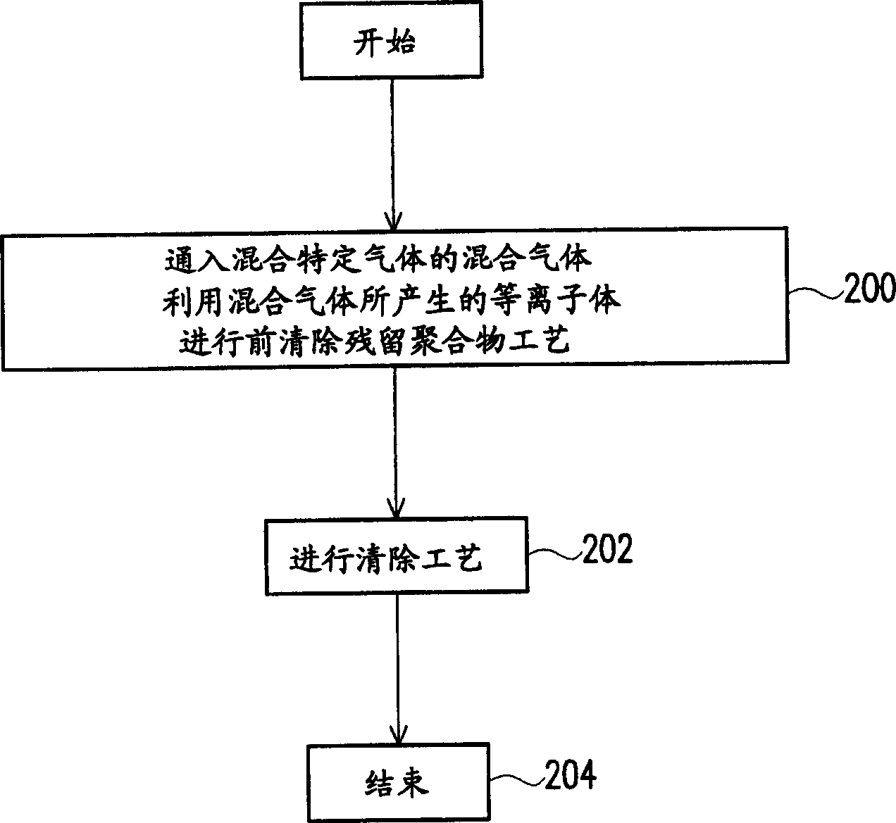
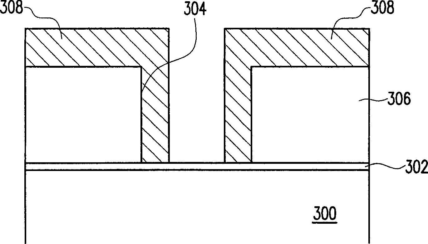
[0034] figure 2 It is a flowchart of steps for removing residual polymers according to another preferred embodiment of the present invention, which can be applied to the removal process of the stop layer (Stop Layer), wherein the stop layer is, for example, a self-aligned contact window (Self Align CONT), no The borderless CONT, the barrier layer for etching the dielectric layer in the dual damascene process, etc., are made of silicon nitride, silicon carbide or silicon oxynitride, for example. In order to illustrate the position of the above-mentioned barrier layer, take the example of etching and removing the barrier layer in the step of forming the via window opening in the dual damascene process, please refer to Figure 3A and Figure 3B A schematic diagram of the manufacturing process for forming via openings and trenches in the dual damascene process is shown.

[0035] Please refer to Figure 3A , a barrier layer 302 has been formed on the substrate 300 , and a diele...


PUM


Abstract

The present invention is residual polymer eliminating method. After etching with reaction gas containing carbon fluoride, mixed gas with mixed specific gas is introduced to produce plasma eliminating residual polymer. The specific mixed gas may be oxygen and nitrogen, argon and hydrogen, argon and nitrogen, or oxygen and argon. The mixed gas producing plasma may be used to soften, burn out or even eliminate residual polymer after etching, and this reduce the technological period.

Description

technical field [0001] The invention relates to a method for cleaning semiconductor process residues, and in particular to a method for pre-cleaning residual polymers (Polymer). Background technique [0002] The dry etching process is a technology that uses the physical phenomenon of particle bombardment to erode thin films. One of the dry etching methods called plasma etching (Plasma Etching) uses plasma to dissociate the molecules of the reactive gas into Reactive ions to the film material, and then through the chemical reaction between the ion and the film, the film exposed to the plasma reacts into a volatile product, which is then vacuumed away for etching of. However, although this method has optimal selectivity, the anisotropy is relatively poor. Therefore, in order to make dry etching have the dual advantages of high selectivity and anisotropic etching, a method called "reactive ion etching" is developed. (Reactive IonEtch, referred to as RIE)" was developed. [0...

Claims


Application Information

Patent Timeline
Patent Type & Authority Applications(China)
IPC IPC(8): C23F1/12H01L21/3065
Inventor 吴燕萍何岳风孙国维洪任谷
Owner UNITED MICROELECTRONICS CORP
Why Eureka
Try Eureka