Heat conductor and its complex machining process

A composite processing and bonding surface technology, which is applied in semiconductor devices, semiconductor/solid-state device parts, instruments, etc., can solve problems such as heat dissipation efficiency bottlenecks, heat transfer obstacles, and inability to improve

Inactive Publication Date: 2004-01-21
简鹏
View PDF0 Cites 5 Cited by
  • Summary
  • Abstract
  • Description
  • Claims
  • Application Information

AI Technical Summary

Problems solved by technology

Among them, one-piece molding methods such as aluminum extrusion method using aluminum material, copper die-casting method of copper material, and powder metallurgy molding method using metal powder materials, the disadvantages of this one-piece molding method are limited Due to the design of the mold cavity space in the mold, the density of the formed fins cannot be too dense and has its limitations, so the heat dissipation efficiency has a bottleneck and cannot be improved.
In addition, composite processing is to use welding methods, such as soldering or silver welding, to weld the fins 52 to the base 51 respectively, and there is also a riveting method that uses cold working to rivet the fins 52 to the base 51. The advantage of this method is that it does not need to be limited by the mold design as the above-mentioned one-piece molding method, so the density of the fins 52 can be increased, but its disadvantage is that there will be certain gaps between the base 51 and the fins 52 due to welding or riveting of different media. Thermal resistance occurs, in other words, because the thermal conductivity of the solder may be lower than the thermal conductivity of the material of the base 51 and the fins 52, so that the solder joints form an obstacle to the heat transfer of the overall heat sink 5, and the base 51 and the fins 52 Because the riveting part is a point joint, not only is it easy to produce local stress concentration in processing, which will affect the stability of the joint surface used in the future, but also in terms of thermal conductivity, because there is only point contact, the heat conduction effect is not ideal.

Method used


Image

  • Heat conductor and its complex machining process
  • Heat conductor and its complex machining process
  • Heat conductor and its complex machining process

Examples


Embodiment Construction

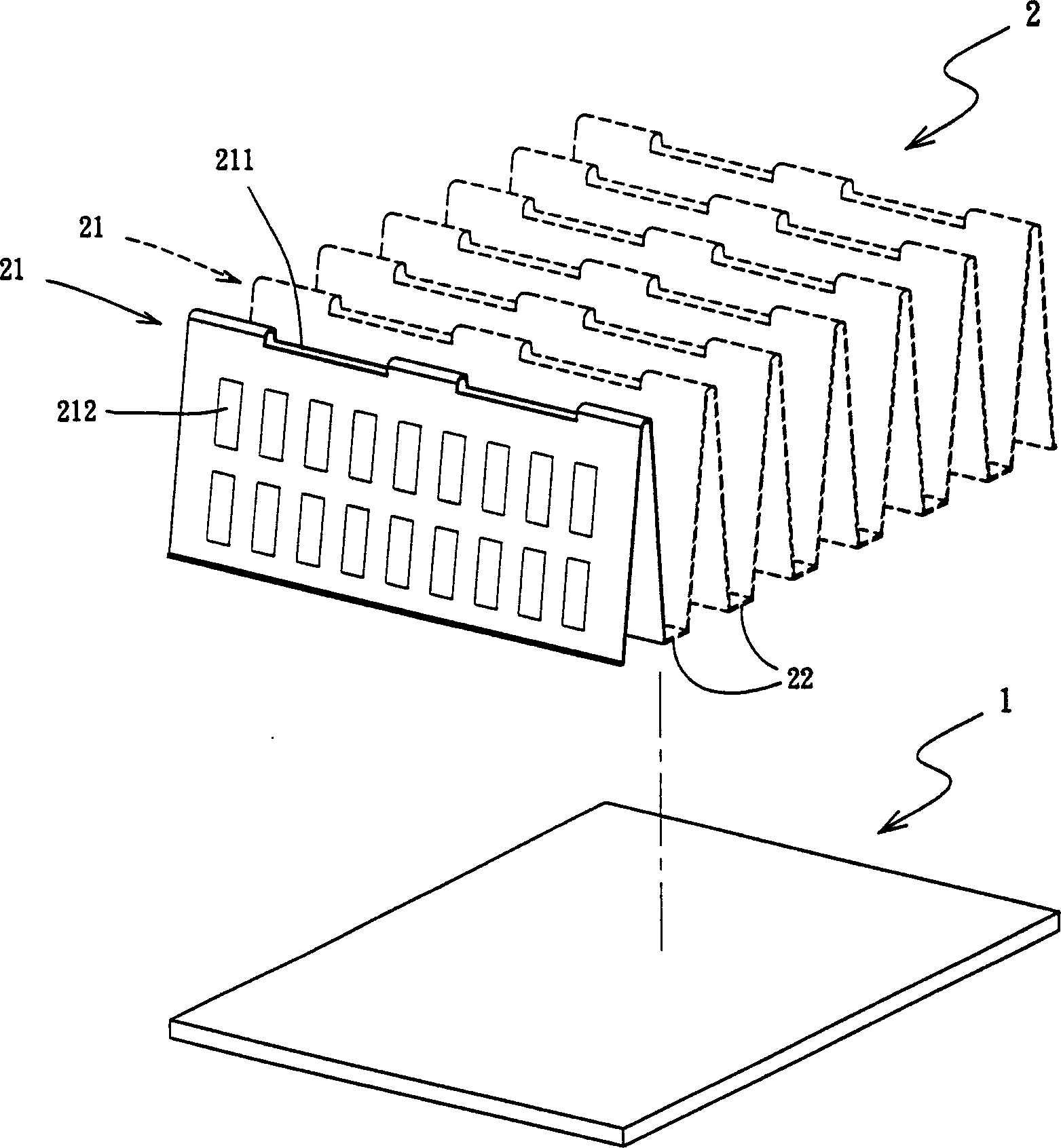
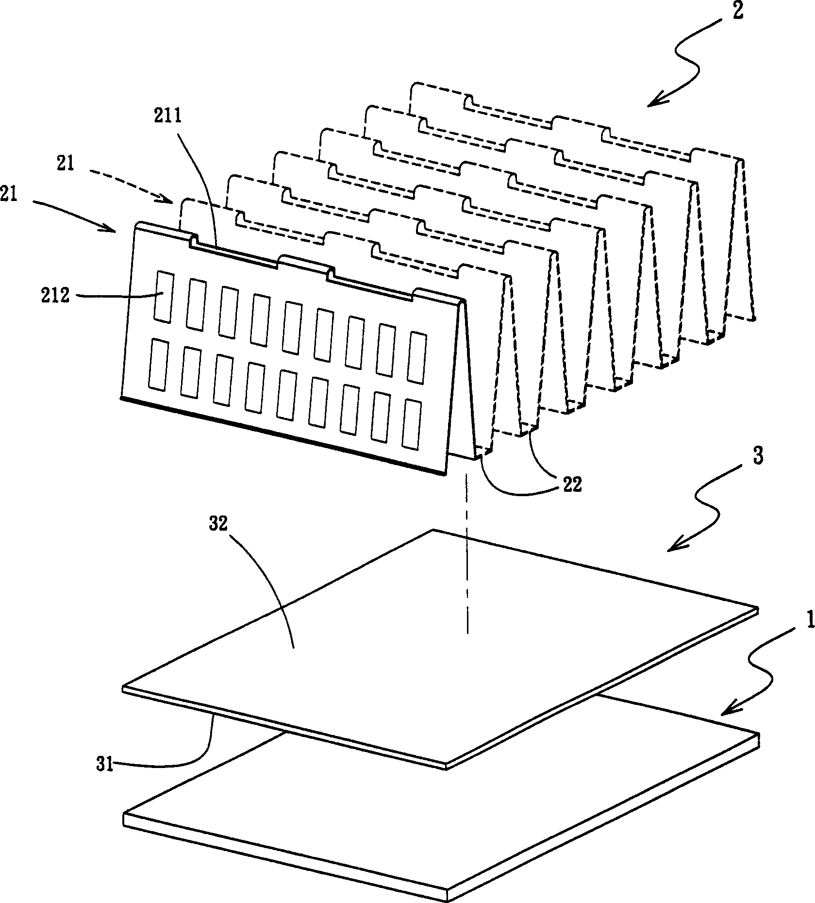
[0047] refer to figure 2The heat conduction device of the present invention comprises a first heat conduction element 1 and a second heat conduction element 2 structurally, the first heat conduction element 1 can be a flat plate with a certain thickness, and its function is similar to the base part of a traditional radiator. It is used to directly or indirectly contact a heat source body, and metal materials with high thermal conductivity such as copper or aluminum can be used in the selection of materials. The second heat conduction element 2 can use the same material or a different material from the first heat conduction element 1, and its shape can be planned according to the internal space of the product actually used, and can be a flat plate (such as a heat spreader or a heat conduction plate simply used to conduct heat) Sheets and other applications), can also be other different shapes, and in this example, the second heat conduction element 2 is repeatedly bent in adva...


PUM


Abstract

The complex machining process of heat conductor includes making the first heat conducting element and at least one second heat conducting element, pressing the second heat conducting element for jointing to the first heat conducting element, and heating the contact surface between the two heat conducting elements while hot forging to form the complex heat conductor. The heat conductor may be used in heat transmitting, heat conducting and heat dissipating assembly in 3C product, and can eliminate heat resistance and raise heat conducting efficiency.

Description

【Technical field】 [0001] The present invention relates to a heat transfer, heat conduction and heat dissipation component used in 3C (information, communication, household appliances) products, in particular to a composite processing method of a heat conduction device and a heat conduction device. 【Background technique】 [0002] Since 3C (information, communication, and home appliances) products are already frequently used electrical products in modern people's lives, because the electronic and electrical components in them will generate more or less heat during use, in order to maintain the normal operation of the product The working temperature, the performance of heat conduction and heat dissipation components will directly affect the stability of product functions. [0003] Such as figure 1 In terms of the structure of the heat sink 5 used by general computer products, it usually has a base 51 and a plurality of fins 52 that are upright and parallel to each other on the...

Claims


Application Information

Patent Timeline
Patent Type & Authority Applications(China)
IPC IPC(8): G06F1/20H01L23/36
Inventor 简鹏
Owner 简鹏
Why Eureka
Try Eureka