Nearinfrared-ray absorbing galss, element, light filter and their production method and copper-contained glass

A technology of near-infrared light and absorbing components, applied in the direction of optical filters, optical components, instruments, etc., can solve the problems of not being able to correct the color sensitivity well, difficult to correct the color sensitivity, and unable to adapt

Inactive Publication Date: 2004-06-30
HOYA CORP
View PDF2 Cites 45 Cited by
  • Summary
  • Abstract
  • Description
  • Claims
  • Application Information

AI Technical Summary

Problems solved by technology

If the transmittance at a wavelength of 400nm drops a little, the color change of the glass can be observed with the naked eye to become more blue, and it is difficult to perform good color sensitivity correction
In order to eliminate this decrease in transmittance, it is also conceivable to reduce the thickness of the glass, but the filter for color sensitivity correction has the following requirements: the color sensitivity must be corrected with a good balance in the entire wavelength range where the imaging element has sensitivity , color sensitivity at other wavelengths cannot be well corrected if the glass is made thin
[0012] In addition, using only high-purity glass raw materials cannot meet the rapidly increasing demand for color sensitivity correction glass for solid-state imaging devices.

Method used


Image

  • Nearinfrared-ray absorbing galss, element, light filter and their production method and copper-contained glass
  • Nearinfrared-ray absorbing galss, element, light filter and their production method and copper-contained glass

Examples


Embodiment 1-12

[0222] The glass raw material Al(PO 3 ) 3 , AlF 3 , Li 2 CO 3 , NaF, MgF 2 , CaF 2 , SrF 2 、BaF 2 , ZnF 2 , Sb 2 o 3 , CuO, etc. were weighed and mixed to obtain the glass composition shown in Table 1 and Table 2. Put it into a platinum crucible, cover it and melt it at 790°C-850°C, stir and defoam, and after homogenization, flow Into the preheated metal mold, forming into the desired shape. The obtained glass molded body was moved into an annealing furnace heated to near the glass transition point, and gradually cooled to room temperature. Samples were cut out from the obtained glass, and various characteristics were measured as described below.

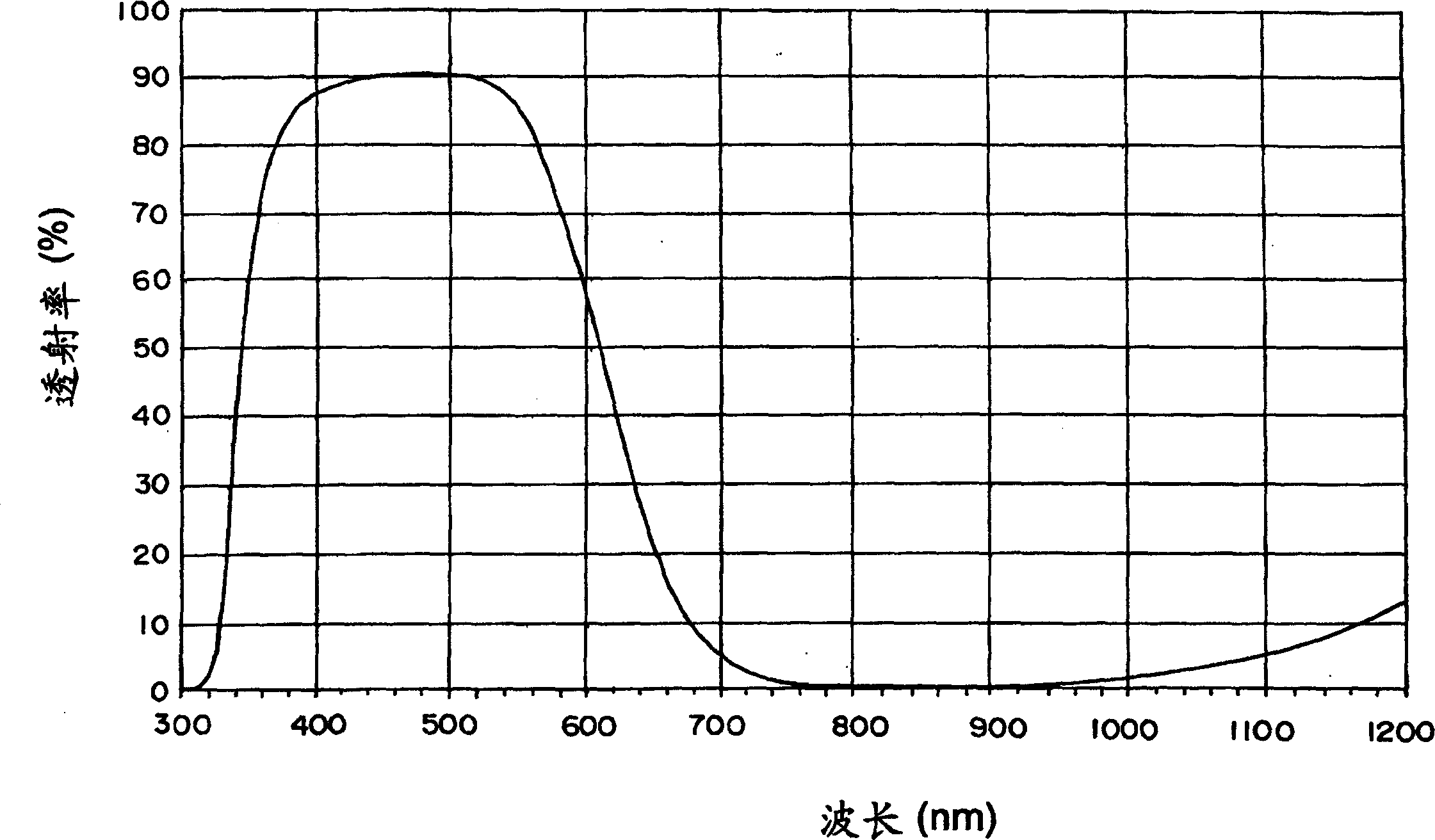
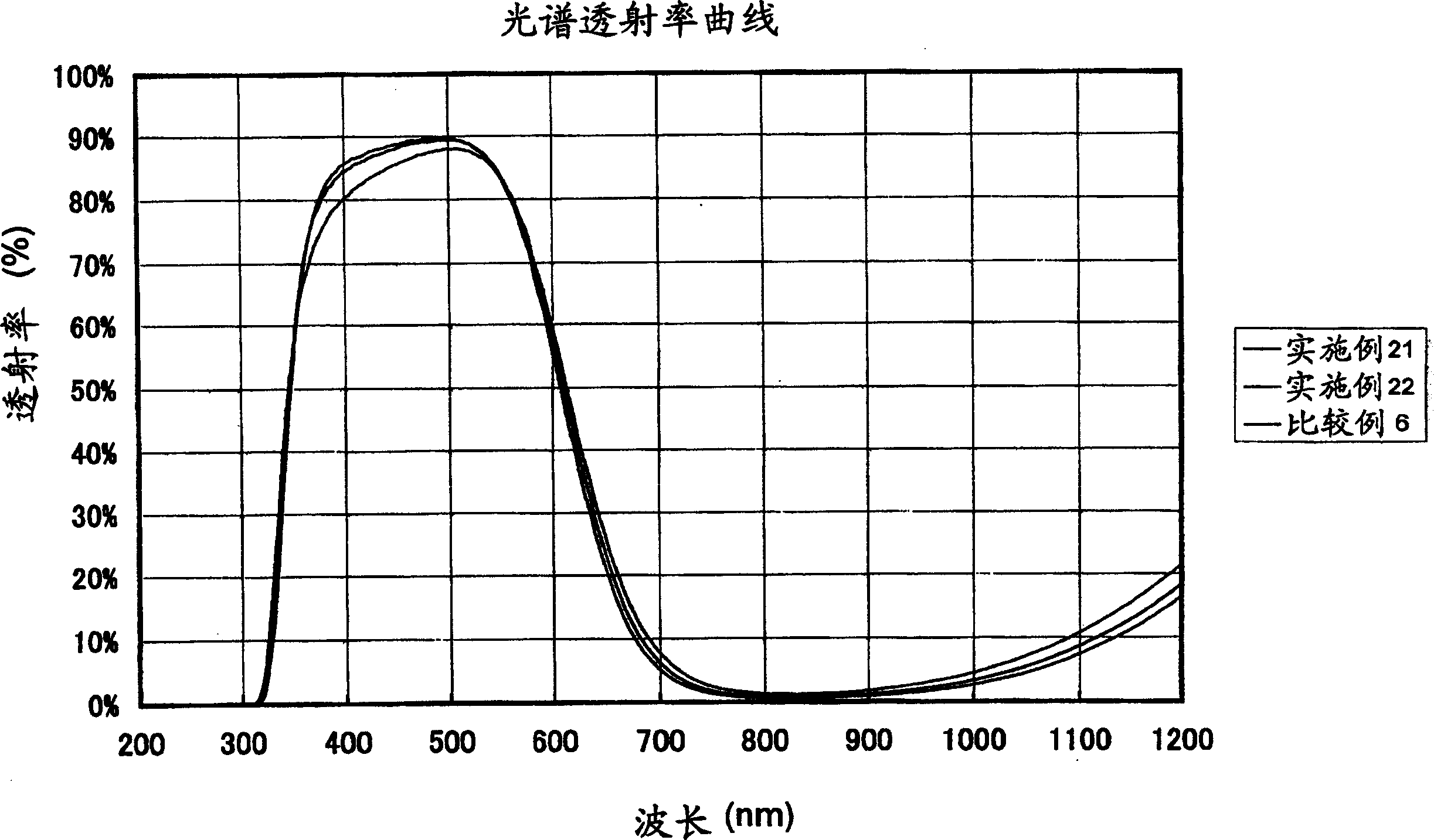
[0223] The spectral transmittance of glass is the transmittance at a wavelength of 200-1200 nm of glass with a thickness of 0.5 mm measured using a spectrophotometer. From the transmittance obtained in this way, the transmittance at each wavelength was calculated in terms of the thickness at which the transmittance is 5...

Embodiment 13

[0238] In the same manner as in Example 1-12, glass was melted, clarified, homogenized, and injected into a mold to form a glass plate made of glass having the same composition as in Example 1-12. After slicing such a glass plate, optical polishing is performed on both sides to obtain a thin plate of desired thickness. This thin plate is cut and processed to obtain a near-infrared light absorbing member having a size required for the above-mentioned thickness. The thickness of the element is a wall thickness with a transmittance of 50% at a wavelength of 615±10nm, and its size is 10mm×10mm˜30mm×30mm. Next, a sheet glass composed of crystal processed into a plate shape and two sheets of optical glass (BK-7) was prepared, and both surfaces of each were optically polished. Then, the optically polished surface is attached to each sheet so that the near-infrared light absorbing element, crystal, and two sheets of BK-7 thin plate glass are laminated on the outermost surface in this...

Embodiment 14

[0240] In the same manner as in Examples 1-12, the glass was melted, clarified, and homogenized to form a molten glass, which flowed down from a platinum nozzle. Then, an appropriate amount of molten glass is put into the mold to form a spherical glass preform. The molded preform is cooled to room temperature first, then reheated and softened in a non-oxidizing atmosphere such as nitrogen or a mixture of nitrogen and hydrogen, and then pressed with a pressing mold. The molding surfaces of the press molding dies are precision-processed in advance into a shape inverting the shape of the target optical element, and these molding surfaces are precisely replicated on the glass in the above-mentioned pressing process. After slowly cooling in the press-molding mold to a temperature at which the glass does not deform, the press-molded optical element is taken out of the molding mold and annealed. In this way, optical elements such as aspherical lenses and diffraction gratings can be ...


PUM

PropertyMeasurementUnit
liquidus temperatureaaaaaaaaaa
thicknessaaaaaaaaaa
thicknessaaaaaaaaaa

Abstract

Provided are near-infrared light-absorbing glass in which good color compensating characteristics are maintained even without containing harmful arsenic, permitting the thinning of the glass, and having good weatherability and forming properties; a near-infrared light-absorbing element comprised of such glass; a near-infrared light-absorbing filter employing such glass. Also provided, at low cost, are near-infrared light-absorbing glass permitting good color compensating, a near-infrared light-absorbing element comprised of such glass, and a near-infrared light-absorbing filter comprising such elements. The glass comprises cationic components with a certain composition as well as F<-> and O<2-> as anionic components. Alternatively, the glass is near-infrared light-absorbing glass, wherein the glass exhibits properties, based on a thickness of 0.5 mm, in the spectral transmittance of wavelengths of 400 to 700 nm, that wavelength, at which a 50 percent transmittance is exhibited, is less than 630 nm, transmittance at a wavelength longer than said wavelength is less than 50 percent, transmittance at a wavelength shorter than said wavelength is higher than 50 percent and the viscosity at a liquid phase temperature is 0.5 Pa.s or more. The near-infrared light-absorbing element is comprised of such glass. The near-infrared light-absorbing filter comprises a glass plate comprised of such glass. Alternatively, the glass is comprised of fluorophosphate glass or phosphate glass, and comprises 0.1 weight percent or more of copper based on CuO, 0.005 to 0.5 weight percent of iron based on Fe2O3, 0.01 to 1 weight percent of antimony based on Sb2O3, and no arsenic.

Description

technical field [0001] The present invention relates to a near-infrared-absorbing glass, a near-infrared-absorbing element, a near-infrared-absorbing filter, and a method for manufacturing a near-infrared-absorbing glass molded body. More specifically, the present invention relates to a near-infrared light-absorbing glass that is suitable for use in near-infrared light-absorbing filters such as color sensitivity correction of solid-state imaging elements such as CCDs, and is excellent in weather resistance and moldability, and the Production of near-infrared light-absorbing elements made of glass and near-infrared light-absorbing filters used as color correction filters for digital cameras and VTR cameras, etc., and glass moldings made of the above-mentioned near-infrared light-absorbing glass method. [0002] Furthermore, the present invention relates to copper-containing fluorophosphate glass or phosphate glass, a near-infrared light absorbing element, and a near-infrared l...

Claims


Application Information

Patent Timeline
Patent Type & Authority Applications(China)
IPC IPC(8): C03C3/16C03C3/247C03C4/08G02B5/20G02B5/22
CPCC03C4/082G02B5/208C03C3/247C03C3/16G02B5/226
Inventor 山根理惠蜂谷洋一邹学禄
Owner HOYA CORP
Why Eureka
Try Eureka