Cutting fool boron nitride composite coating layer and its preparation method

A cutting tool and composite coating technology, applied in the direction of coating, turning equipment, tools for lathes, etc., can solve the problem of not proposing a better process method for coating, and achieve the effect of improving processing efficiency

Inactive Publication Date: 2004-07-21
XIANGTAN UNIV
View PDF3 Cites 32 Cited by
  • Summary
  • Abstract
  • Description
  • Claims
  • Application Information

AI Technical Summary

Problems solved by technology

It just puts forward the idea of ​​coating, and does not propose a better process method for preparing coating

Method used


Image

  • Cutting fool boron nitride composite coating layer and its preparation method
  • Cutting fool boron nitride composite coating layer and its preparation method
  • Cutting fool boron nitride composite coating layer and its preparation method

Examples


Embodiment Construction

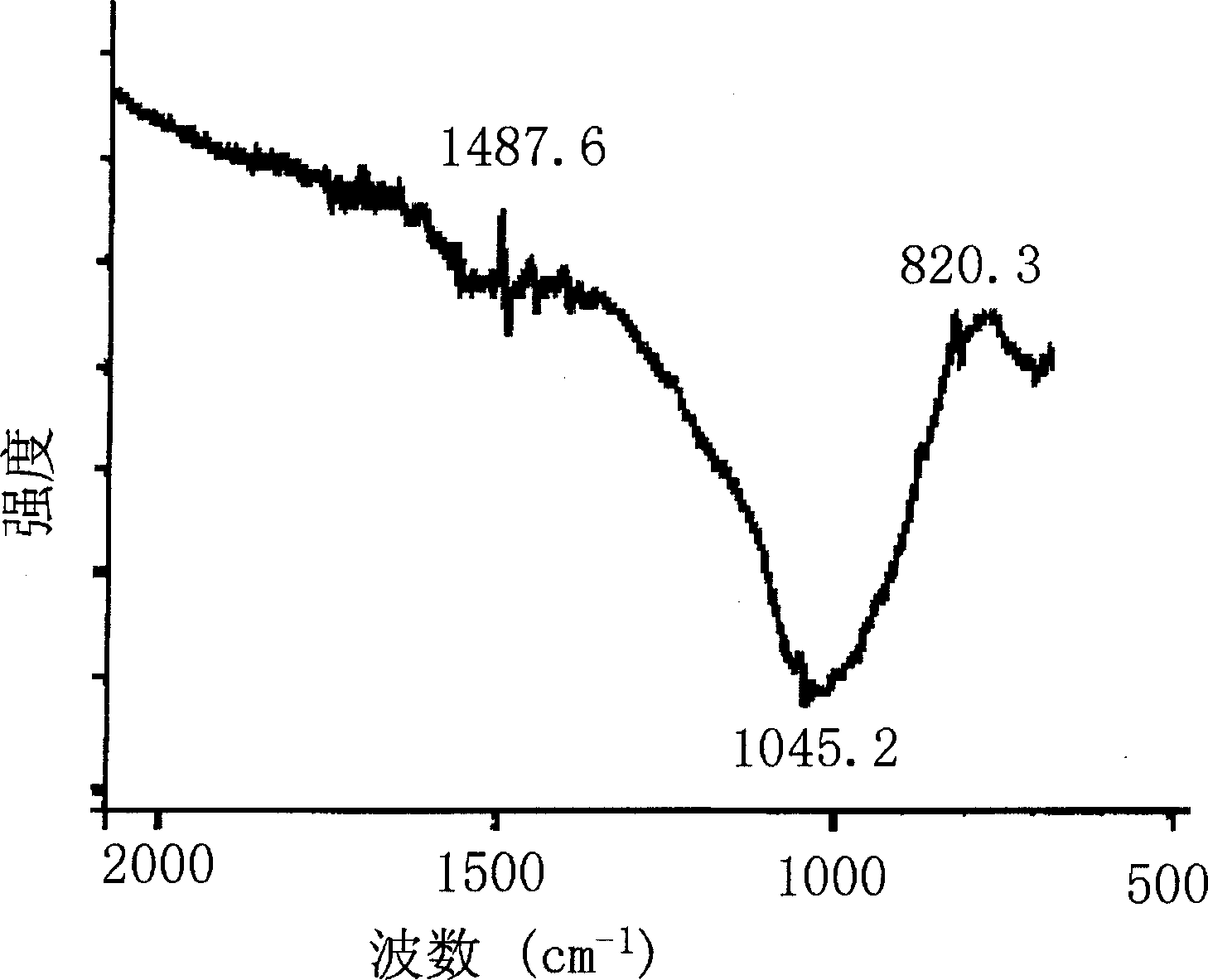
[0015] The invention adopts plasma enhanced pulse laser deposition method and hot wire assisted radio frequency plasma chemical vapor deposition method. from figure 2 It can also be seen from the scanning electron microscope pictures of the tool coating prepared by plasma-enhanced pulsed laser deposition that the c-BN crystal grains are mostly square, and they are relatively evenly distributed on the tool.

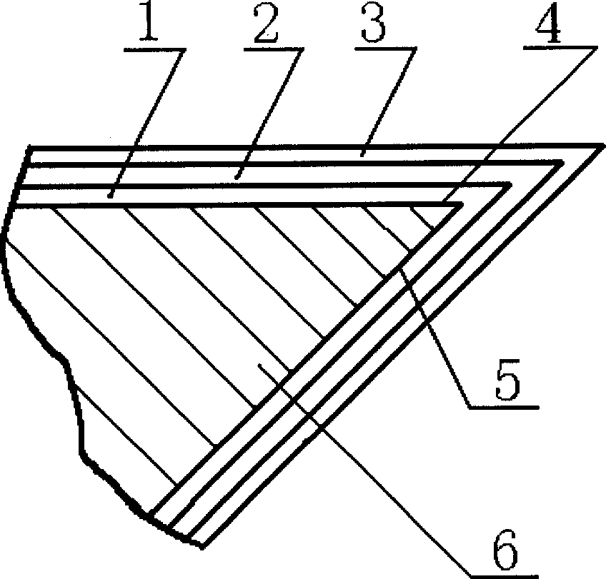
[0016] Depend on figure 1 It can be seen that the boron nitride coated tool, including the coated insert, is composed of a cemented carbide substrate and a coating combination. The coating combination includes a base layer combined with cemented carbide, an intermediate layer and an outermost layer. Boron nitride layer, the coated tool can be used for mechanical cutting operations, including turning, drilling, milling, planing, reaming or similar chip processing. The cemented carbide substrate includes YG, YT, YW and YN types, and may also be the cemented carbide substr...


PUM

PropertyMeasurementUnit
thicknessaaaaaaaaaa
thicknessaaaaaaaaaa
thicknessaaaaaaaaaa

Abstract

A coated composite boron nitride layer on the surface of cutting tool is composed of a substrate layer which is TiCxOyNz layer directly deposited on the hard alloy cutter, an intermediate binding layer which is made of Ni, Ni-contained compound, or N or B contained compound, and a boron nitride layer prepared from cubic boron nitride. Said coated layer is prepared by plasma intensified pulse laser deposition method, or hot wire added RE plasma CVD method, or their combination.

Description

technical field [0001] The invention relates to a coating for a cutting tool and a preparation method thereof, in particular to a boron nitride composite coating for a cutting tool and a preparation method thereof. technical background [0002] As technology advances, metal removal rates continue to increase. In 1900, it took 100 minutes to turn a standard steel bar (φ500mm×100mm (length)) with carbon tool steel, and the advanced cemented carbide that appeared in the 1950s reduced the processing time to a few minutes. Coated carbide tools were introduced in 1969 and have improved since then. The original coated inserts cut standard steel rods in 1.5 minutes, while the GC1025 and GC015 coated inserts further reduced the processing time to 1.25 minutes and 1 minute. If all processing factors are considered, the most economical way is to obtain various new tool materials to increase cutting speed and reduce cutting cost. Because the tool coating can not only improve the surf...

Claims


Application Information

Patent Timeline
Patent Type & Authority Applications(China)
IPC IPC(8): B23B27/14B23P15/28C23C16/34C23C16/38
Inventor 周里群李玉平
Owner XIANGTAN UNIV
Why Eureka
Try Eureka