Photosensitive planography printing plate
A lithographic printing plate, printing plate technology, applied in lithographic printing equipment, printing, printing process and other directions, can solve the problems of inability to meet the sensitivity, developing ink acceptability, color resistance and printing durability.
- Summary
- Abstract
- Description
- Claims
- Application Information
AI Technical Summary
Problems solved by technology
Method used
Image
Examples
Embodiment approach 1
[0230] Sulfuric acid concentration: 100-200 g / liter (more preferably 130-180 g / liter).
[0231] Aluminum ion concentration: 2-10 g / liter (more preferably 3-7 g / liter).
[0232] Liquid temperature: 15-40°C (more preferably 33-38°C).
Embodiment approach 2
[0234] Sulfuric acid concentration: 50-125g / liter (more preferably 80-120g / liter).
[0235] Aluminum ion concentration: 2-10 g / liter (more preferably 3-7 g / liter).
[0236] Liquid temperature: 40 to 70°C (more preferably 50 to 60°C).
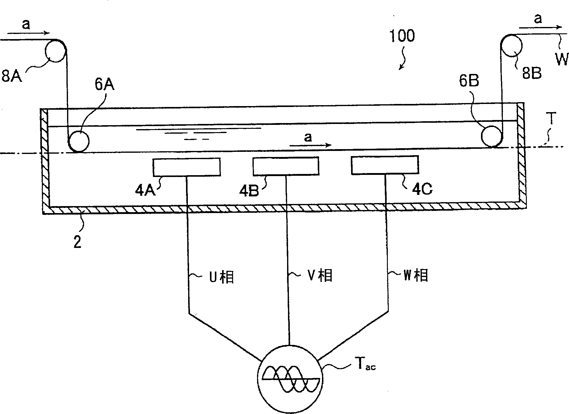
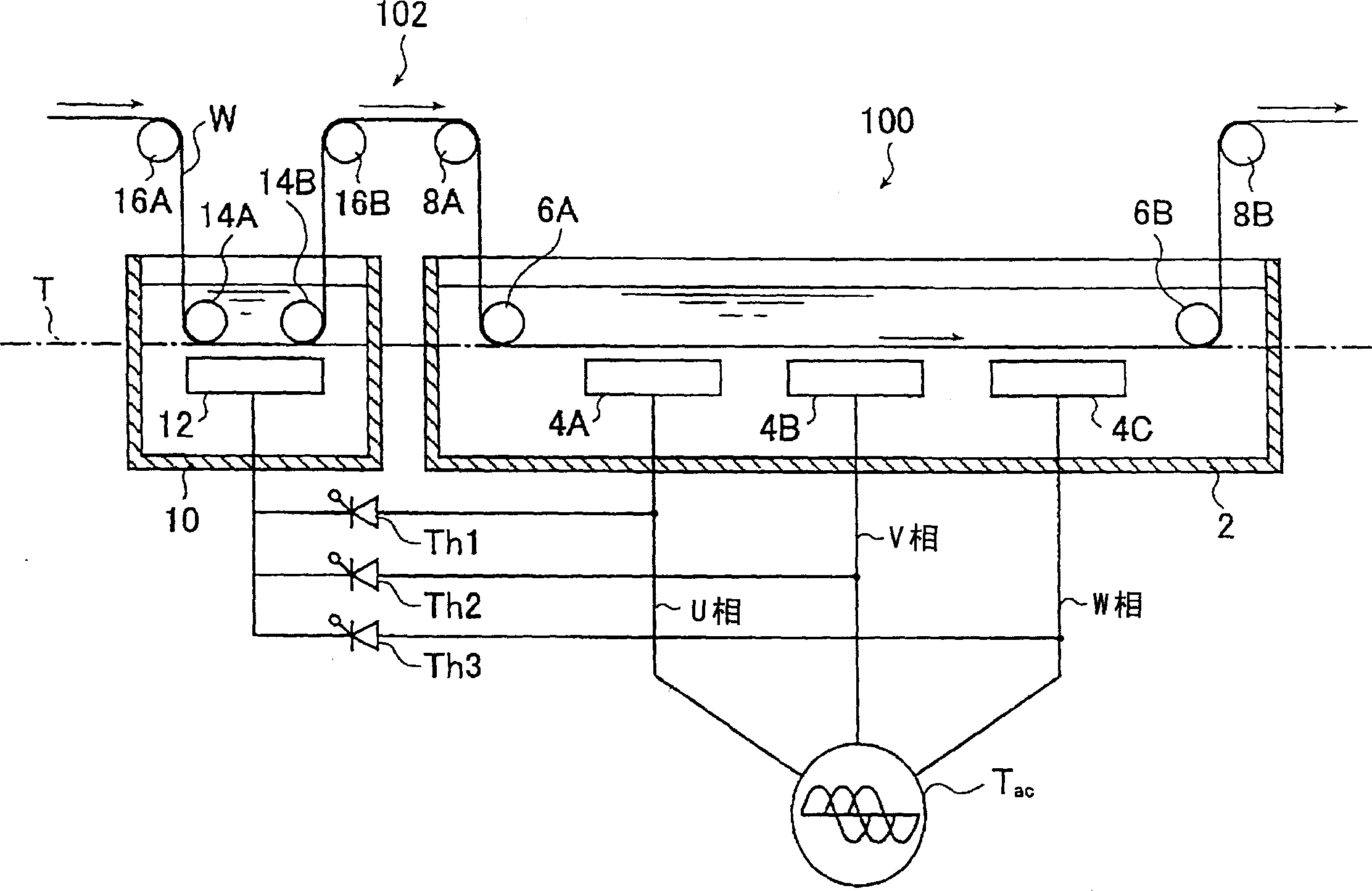
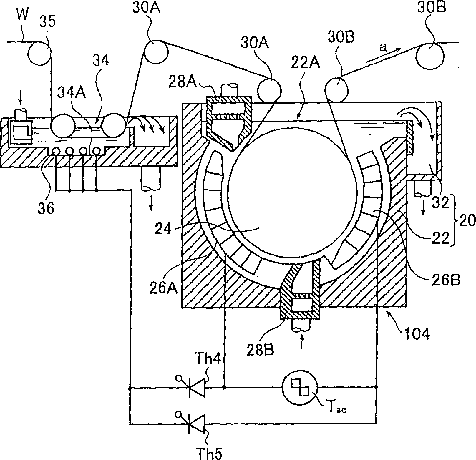
[0237] Any one of the direct power system that directly energizes the aluminum plate through the conductive roller and the liquid power system that indirectly energizes the aluminum plate through the electrolyte can be used as the power source for anodizing the aluminum (alloy) plate.
[0238] For direct power systems, low-speed and low-current anodizing devices are generally used, in which aluminum (alloy) plates are conveyed at a lower line speed of 30m / min or less; as for indirect power systems, high-speed and high-current are generally used Anodizing plants where the plates are conveyed at high line speeds exceeding 30m / min.
[0239] For indirect power systems, gable or linear cell designs can be used, for example as described in Continuou...
Embodiment 1~6 and comparative example 1~4
[0633]
[0634] JIS-A-1050 aluminum plates with a thickness of 0.3 mm were processed into supports A, B, C, D and E in the following manner.
[0635] (Carrier A)
[0636] An aluminum plate (JIS-A-1050) with a thickness of 0.3mm was etched with a solution containing 30g / liter of sodium hydroxide and 10g / liter of aluminum ions at 60°C for 10 seconds, then washed with running water, and neutralized with nitric acid (12g / liter ), and then washed with water. Put the board into a treatment liquid containing 15 g / liter of hydrochloric acid and 10 g / liter of aluminum ions at 30° C., apply a 50 Hz sine wave alternating current, and perform electrolytic surface roughening. The current density is 16A / dm 2 , power is 400C / dm 2 . Then wash with water. Then, etch at 35°C for 10 minutes with a solution containing 36g / liter of sodium hydroxide and 10g / liter of aluminum ions, rinse with running water, and carry out desmutting for 10 seconds in a sulfuric acid aqueous solution containing...
PUM
| Property | Measurement | Unit |
|---|---|---|
| Average opening diameter | aaaaa | aaaaa |
| Average opening diameter | aaaaa | aaaaa |
| Average opening diameter | aaaaa | aaaaa |
Abstract
Description
Claims
Application Information
 - R&D
- Intellectual Property
- Life Sciences
- Materials
- Tech Scout
- Unparalleled Data Quality
- Higher Quality Content
- 60% Fewer Hallucinations
Browse by: Latest US Patents, China's latest patents, Technical Efficacy Thesaurus, Application Domain, Technology Topic, Popular Technical Reports.
© 2025 PatSnap. All rights reserved.Legal|Privacy policy|Modern Slavery Act Transparency Statement|Sitemap|About US| Contact US: help@patsnap.com


