

Masking material
A technology of polymers and alloys, applied in the direction of injection devices, etc., can solve problems such as cracks, cracks, poor fluidity of melts, and poor formability
- Summary
- Abstract
- Description
- Claims
- Application Information
AI Technical Summary
Problems solved by technology
Method used
Image

Examples
Embodiment 1
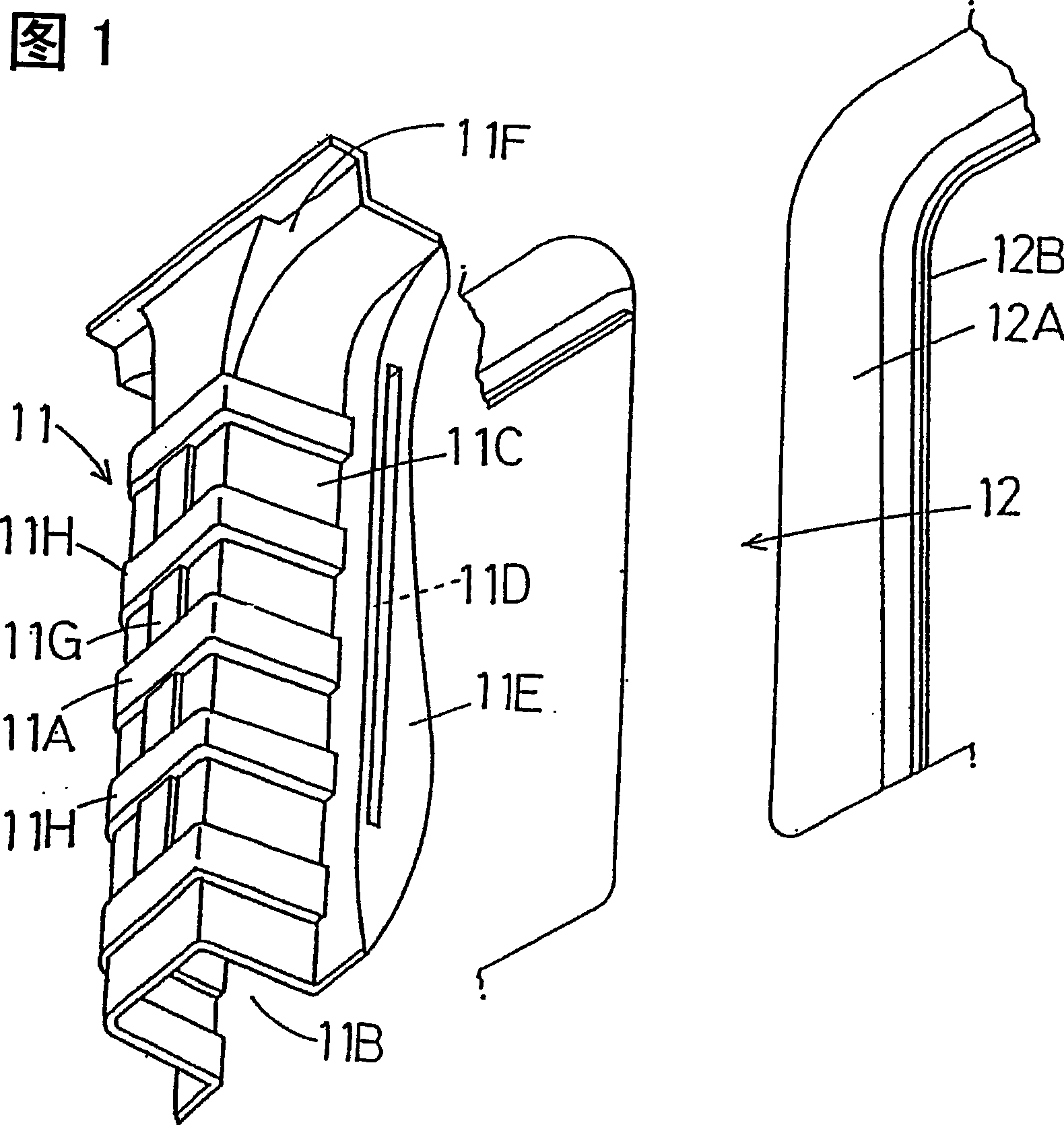
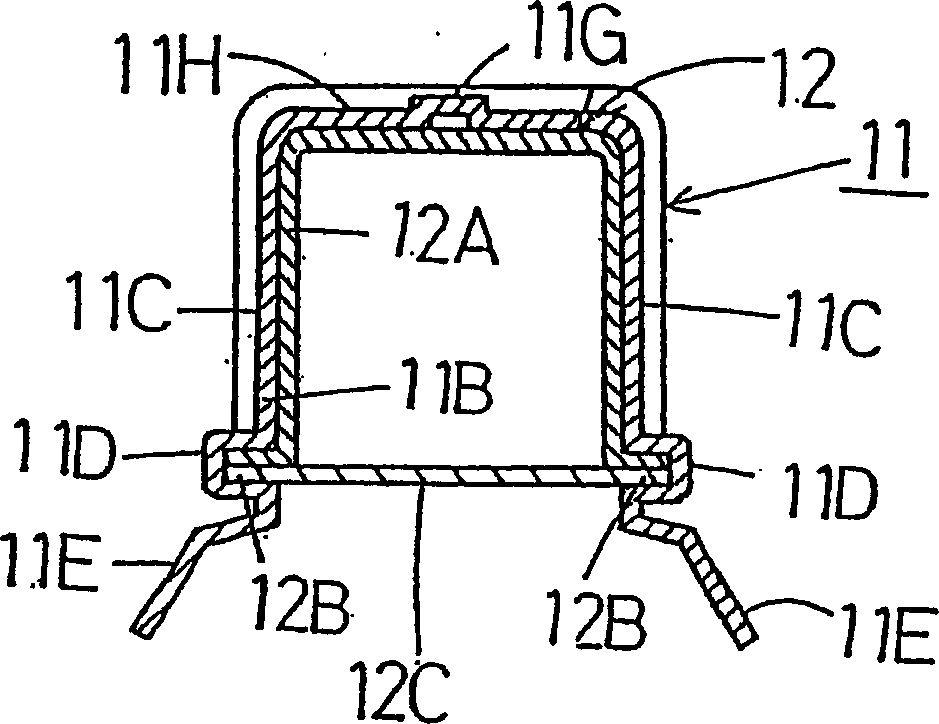
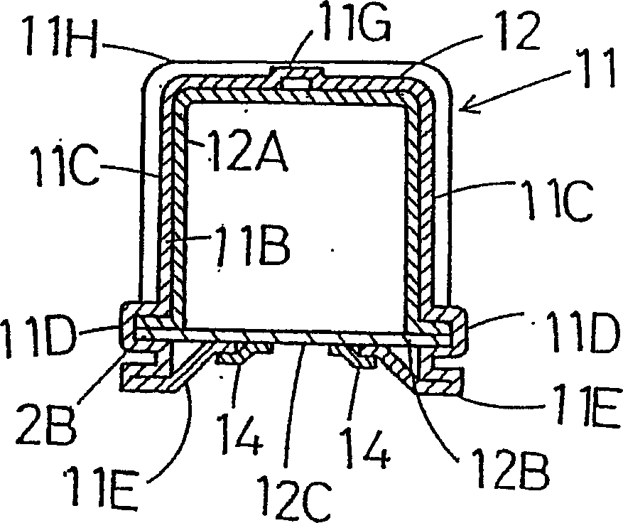
[0064] Figure 1~ Figure 4 Example 1 of the present invention is shown. The shielding material 11 of this embodiment is used, for example, to shield a columnar body such as the center pillar 12 of an automobile. Then, the shielding material 11 is a body 11A with a U-shaped cross section formed by the fitting portion 11B of the body 12A forming the middle column 12 inside, and the lower edge of the side walls 11C and 11C that are fitted along the body 11A. The formed flange fitting portions 11D, 11D of the center column 12, the back support portions 11E, 11E extended from the flange fitting portions 11D, 11D of the flanges 12B, 12B, and the upper support portions extending from the upper portion. The supporting portion 11F is composed of the reinforcing ribs 11G in the longitudinal direction and the reinforcing ribs 11H in the width direction are formed in the main body 11A. The masking material 11 is obtained by mixing 5 mass parts of a polymer alloy (40:60 mass ratio) having...
Embodiment 2
[0069] Figure 5 Example 2 of the present invention is shown. The shielding material 21 of this embodiment is a body 21A having a U-shaped cross-section obtained by forming the fitting portion 21B of the body 22A of the middle column 22 on the inside, and the bottom of the side walls 21C and 21C fitted along the body 21A. The flange fitting portion 21D, 21D of the flange (22B, 22B) of the intermediate column 22 formed by the edge, and the back support portion 21E, 21E extending from the flange fitting portion 21D, 21D, and extending Composed of the upper supporting part 21F on the upper part, the reinforcement ribs 21G in the longitudinal direction and the reinforcement ribs 21H in the width direction are formed around the main body 21A. However, this embodiment is different from the situation in Embodiment 1 in that the reinforcement in the longitudinal direction is interrupted. Rib 21G. The masking material 21 is obtained by adding and mixing 15 parts by mass of SBS and 10...
Embodiment 3
[0074] Figure 6 ~ Figure 8 Representing Embodiment 3 of the present invention, Figure 633 in the figure is the body of the automobile. When painting, the shielding material 31 of the embodiment is attached to the air inlet 36 of the lower side fender portion 35 of the front bumper 34 . Inside the air suction port 36 of the baffle part 35, vertical and horizontal reinforcing grids 36A, 36B and a pair of left and right pillars 36C are provided. And vertical and horizontal fitting grooves 32A, 32B and fitting groove 32C are formed, and a flange 32D is formed around the front surface, and an adhesive layer 32E is formed around it. In addition, the fitting grooves 32A, 32B, and 32C, which are fitted with the reinforcement grids 36A, 36B and the pillars 36C, function as ribs for reinforcing the masking material 31 . At the intersection of the fitting groove 32B in the width direction (longitudinal direction) and the fitting groove 32A in the longitudinal direction (horizontal di...
PUM
| Property | Measurement | Unit |
|---|---|---|
| Thickness | aaaaa | aaaaa |
Abstract
Description
Claims
Application Information