Method and apparatus for producing steel-plastic composite pipe

A technology of steel-plastic composite pipe and production method, which is applied in the direction of pipes, rigid pipes, pipes/pipe joints/pipe fittings, etc., and can solve the problems of high, no measures, compounding together, affecting the reliability and strength of mutual melting and bonding

Inactive Publication Date: 2005-09-28
甘国工
View PDF3 Cites 18 Cited by
  • Summary
  • Abstract
  • Description
  • Claims
  • Application Information

AI Technical Summary

Problems solved by technology

This kind of pipeline not only has the higher pressure bearing capacity of metal pipelines, but also has a plastic inner and outer wall and connects the inner and outer walls through the holes of the metal skeleton, so it has better anti-corrosion performance and pipeline connection performance. It is compatible with metal pipelines and Compared with pure plastic pipes, it has better comprehensive performance, and has been widely used in chemical industry, oil transportation, gas transportation, pressure transportation and corrosive media. It is a better structural composite pipe, but according to the above patents In the technical schemes, the molten polymer continuum passes through the holes of the metal skeleton to form the inner and outer pipe walls at the same time. This molding method has great defects. The molten polymer continuum turns over to The other side is melted and combined with each other. The turbulent flow of the polymer over the metal skeleton will leave a lot of residual stress in the cooled plastic pipe wall, which will lead to easy cracking during the use of the pipe and reduce the service life of the pipe. And this flow mode will destroy the thin layer of adhesive layer that is extruded or sprayed or covered on the inner and outer surfaces of the metal skeleton, especially in the pores, resulting in a direct bond between the polymer continuum and the metal skeleton surface rather than through bonding. The agent layers are firmly combined with each other, while the polymer continuum is a non-polar surface, and the metal skeleton surface is a polar surface, the two cannot really be firmly combined with each other, resulting in mutual delamination during transportation or installation or use , In addition, the temperature of the polymer mutual fusion bonding surface is lowered due to the crossover of the metal skeleton, which also affects the reliability and strength of mutual fusion bonding
Patent 00100446.8 discloses a steel-plastic composite pipe forming device, including an inner pipe extruder, an outer pipe extruder, a glue coating device, a steel strip coil forming device and a steel strip coil welding machine. The device can produce There is a steel-plastic composite pipe with inner and outer plastic pipe walls and metal steel plates bonded together. However, there is a big defect in the welding method of the steel plate seams in this technical solution, that is, the temperature of the weld seam is very high after welding, and no

Method used


Image

  • Method and apparatus for producing steel-plastic composite pipe
  • Method and apparatus for producing steel-plastic composite pipe
  • Method and apparatus for producing steel-plastic composite pipe

Examples


Embodiment 1

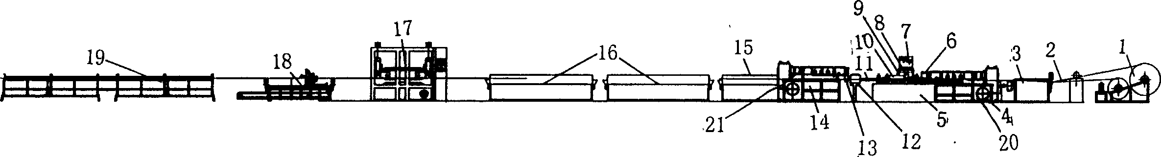
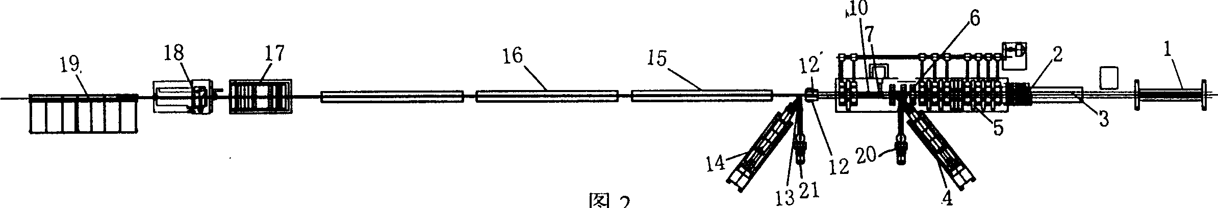
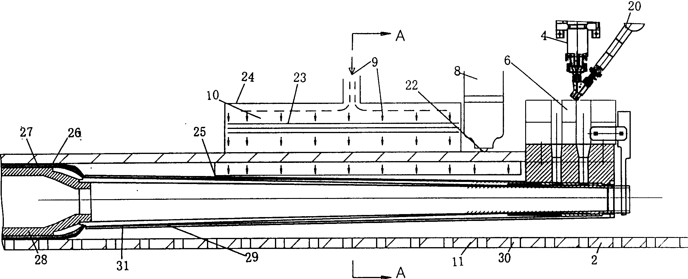
[0039] figure 1 - Figure 4, which shows a diagram of Embodiment 1 of the present invention. see figure 1 , Figure 2, according to the sequence of the composite pipe forming process, an unwinding machine 1 with a perforated steel strip 2, a continuous butt welding mechanism for the perforated steel strip 3, a core tube extruder 4, and an adhesive extruder 20 are arranged , Cylindrical perforated steel framework forming mechanism 5, core layer tube and core tube surface adhesive co-extrusion die head 6, cylindrical perforated steel framework welding mechanism 7, welding nozzle 8, filling weld seam protection device 10 Inert gas 9, welded cylindrical perforated steel frame 11, cylindrical perforated steel frame heater 12, co-extrusion die head 13 of the outer layer tube with adhesive layer on the inner surface, outer layer Pipe extruder 14, outer layer binder extruder 21, composite pipe cooling calibrating box 15, composite pipe spray cooling water tank 16, composite pipe tract...

Embodiment 2

[0042] figure 1 , Fig. 2, Fig. 5 have provided embodiment 2 figure of the present invention. Embodiment 2 is basically the same as Embodiment 1. The difference is that an inflatable tube 32 is installed on the co-extrusion die 6 as shown in FIG. , the inflated airbag will cling to the core tube on the inner surface of the metal skeleton.

Embodiment 3

[0044] figure 1 ,figure 2, Image 6 Figure 3 of Embodiment 3 of the present invention is given. Embodiment 3 is basically the same as Embodiment 1. The difference is as Image 6 In the extrusion die head 35 shown in the cylindrical metal skeleton 11 that has been welded and formed, there are respectively a core layer pipe extrusion flow channel 37 and an adhesive layer extrusion flow channel 36. In the repair ring 34 (or Under the action of scraper), the first extruded adhesive layer 26 is closely attached to the inner surface of the metal skeleton, and then the core layer tube 27 is extruded, and under the action of the inner sizing rod 28 (or plugging), the core layer tube 27 is compounded on the inner surface of the metal skeleton through the adhesive layer 26. The step-by-step method is used to extrude the adhesive layer separately on the inner surface of the metal skeleton, and then extrude the core layer tube on the adhesive layer, which is beneficial to separately a...


PUM


Abstract

The composite steel/plastic pipe producing process includes longitudinally bending or spirally winding steel plate with holes and welding to form metal pipe skeleton, separating the welded metal pipe skeleton from atmosphere with inert air, extruding the core layer plastic pipe inside the metal pipe skeleton, extruding the outer layer plastic pipe outside the metal pipe skeleton and making the inner layer and the outer layer of plastic pipe combined into one integral via the holes in the metal skeleton. The present invention also provides one composite steel/plastic pipe producing line. The produced composite steel/plastic pipe has high bearing capacity and firm combination of the inner and outer plastic layers.

Description

Technical field: [0001] The invention relates to a production method of a steel-plastic composite pipe, in particular to a method of using an inert gas protection device to isolate the welding seam from the outside air at the welding place of a cylindrical metal skeleton with holes from the welding point along the welding seam to prevent Oxidized layers are formed on the inner and outer surfaces of the welding seam, and the production method and device of compounding the adhesive layer, the core layer tube and the outer layer tube on the inside and outside of the cylindrical metal frame with holes respectively. Background technique: [0002] There are many methods and devices for the production technology of steel-plastic composite pipes, as well as corresponding patents, which use a metal skeleton with holes as a reinforcement, and extrude a composite polymer material on the skeleton as a continuum to wrap the skeleton to form a steel-plastic composite pipe. The reports and...

Claims


Application Information

Patent Timeline
IPC IPC(8): B21C37/06B29C47/02F16L9/147
Inventor 甘国工
Owner 甘国工
Why Eureka
Try Eureka