Hard coating and its production method

A protective film, hard technology, applied in metal material coating process, vacuum evaporation plating, coating, etc., can solve the problem of not meeting the lubricity requirements of dry cutting conditions

Inactive Publication Date: 2005-12-21
HITACHI TOOL ENG LTD
View PDF7 Cites 8 Cited by
  • Summary
  • Abstract
  • Description
  • Claims
  • Application Information

AI Technical Summary

Problems solved by technology

[0015] However, the hard coatings of Japanese Patent No. 3416938 and Japanese Patent Laid-Open No. 2001-293601 only maintain oxida

Method used


Image

  • Hard coating and its production method
  • Hard coating and its production method
  • Hard coating and its production method

Examples


Embodiment 1

[0066] Embodiment 1, comparative example 1

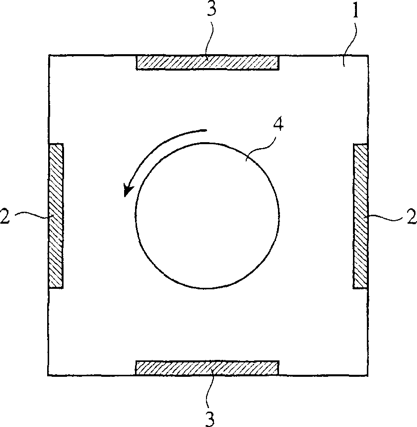
[0067] In Example 1, such as figure 1 As shown, a hard protective film was formed on a cemented carbide insert substrate mounted on a rotary table 4 using a small vacuum device 1 including an AIP target 2 and an MS target 3 as an evaporation source. Both AIP target 2 and MS target 3 use TiAl alloy. Use N 2 gas as a reactive gas. The pressure of the reaction gas was set to 3.0 Pa, and plasma was generated simultaneously by the AIP method and the MS method. The substrate temperature was set to 400°C, and the bias voltage was set to -40V to -150V. In addition, in Comparative Example 1, a hard film was formed on the insert under the same conditions as in Example 1 except that only the AIP method was used.

[0068] The (TiAl)N hard film obtained in Example 1 has high toughness, and also has a multilayer structure composed of layer 21 obtained by the AIP method and layer 22 obtained by the MS method. In this multilayer structure, cr...

Embodiment 2~15

[0069] Examples 2-15, Comparative Examples 2-14 and Conventional Examples 1-5

[0070] In Examples 2-15, such as figure 1 As shown, a hard protective film was formed on a cemented carbide insert substrate mounted on a rotary table 4 using a small vacuum device 1 including an AIP target 2 and an MS target 3 as an evaporation source. As shown in Table 1, the AIP target 2 is an alloy of various compositions, and the MS target 3 is a metal silicide. Reactive gas is used in an appropriate combination of N and N according to the composition of the target hard film. 2 Gas, CH 4 Gas and Ar / O 2 One or two or more of the mixed gases. In order to make the silicon content of the hard protective film change periodically and smoothly in the lamination direction, the pressure of the reaction gas is set to 3.0 Pa, and the plasma is generated simultaneously by two film-forming methods of the AIP method and the MS method. The discharge power of the MS target 3 in each Example and Comparati...

Embodiment 15

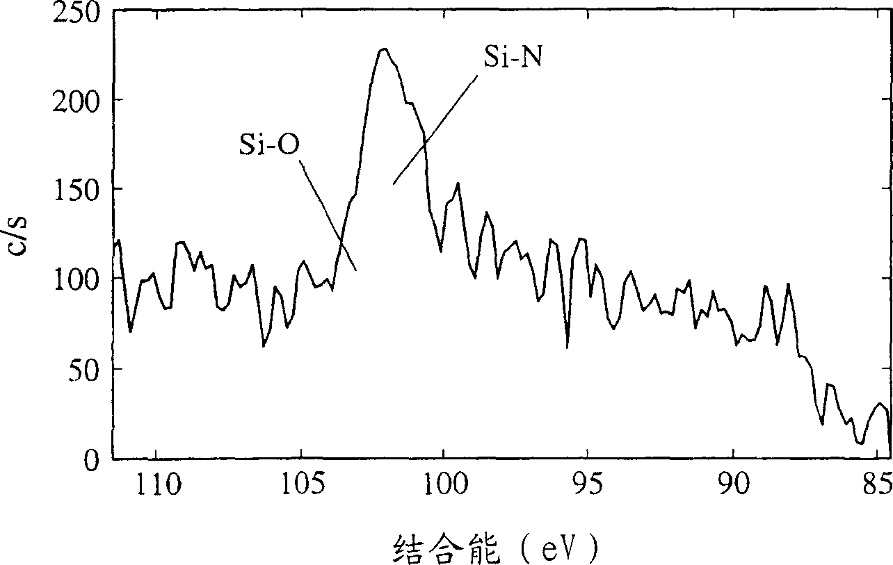
[0117] A hard protective film was formed on the insert in the same manner as in Example 14, except that oxygen was not added to the reaction gas. The structure of the obtained hard film was columnar, the lattice bands were continuous, and the average thickness of one layer was 33.6 nm. In addition, the Si content in the hard film is 6.3 atomic %, and Si A 10.7 at%, Si B 1.9 at%, with a difference in Si content, but no Si-O bond. Therefore, the cutting distance is 19.4m.


PUM

PropertyMeasurementUnit
The average thicknessaaaaaaaaaa

Abstract

The present invention relates to a kind of hard protection film, and this hard protection film is the hard protection film that forms by physical vapor deposition method, is made of transition metal elements selected from Group 4a, 5a and 6a of the periodic table, Al and B At least one metal element of Si and at least one non-metallic element selected from C, N and O, the above-mentioned hard protective film has a columnar structure, and the columnar structure has a plurality of layers with different Si contents In the formed multi-layer structure, the lattice bands are continuous in the boundary region between the above-mentioned layers, and the thickness of each layer is 0.1-100 nm.

Description

technical field [0001] The present invention relates to a hard protective film excellent in wear resistance, adhesion, high temperature oxidation resistance and toughness formed on substrates such as superhard alloy, cermet, high speed steel and mold steel, and the hard protective film Manufacturing method of protective film. Background technique [0002] As metal cutting reaches a high speed with the amount of cutting edge per blade exceeding 0.3mm, in the existing hard protective film coated tools, the oxidation resistance, wear resistance, fusion resistance, and resistance to hard protective film The detachability and the like are increasingly becoming unfavorable. For this reason, various technologies for improving the oxidation resistance, abrasion resistance, fusion resistance, peeling resistance, etc. of the hard film have been proposed. [0003] Japanese Patent Application Laid-Open No. 2003-225807 discloses a cutting tool, the cutting tool is, on the substrate of ...

Claims


Application Information

Patent Timeline
IPC IPC(8): C23C14/06
Inventor 久保田和幸
Owner HITACHI TOOL ENG LTD
Why Eureka
Try Eureka