Light emitting device

A light-emitting device and excitation light technology, applied in the direction of light-emitting materials, signal devices, lighting devices, etc., can solve problems such as deterioration, color deviation, heat generation, etc., and achieve the effects of preventing heat generation and deterioration, improving light output, and preventing deterioration.

Active Publication Date: 2006-06-21
NICHIA CORP
View PDF2 Cites 14 Cited by
  • Summary
  • Abstract
  • Description
  • Claims
  • Application Information

AI Technical Summary

Problems solved by technology

[0007] However, since the optical density of the semiconductor light-emitting element is very high, the resin and fluorescent material constituting the wavelength conversion member generate heat and deteriorate due to the high-density excitation light.
Therefore, there are also problems such as shortening the lifetime of the light-emitting device itself, or being unable to sufficiently emit light from the semiconductor light-emitting element to the outside.
[0008] In addition, since laser diodes have a narrower half-radius than light-emitting diodes, in conventional endoscope devices that use red, green, and blue laser diodes to realize white light sources, color t

Method used


Image

  • Light emitting device
  • Light emitting device
  • Light emitting device

Examples


Embodiment 1

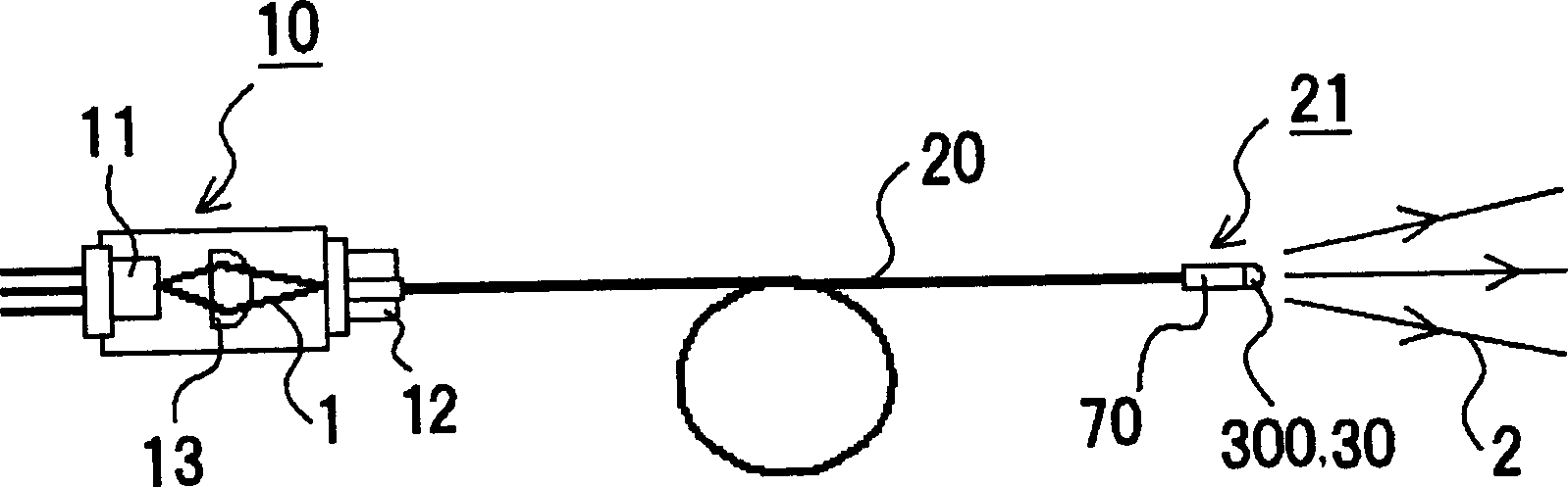
[0236] like figure 1 As shown, the light-emitting device of this embodiment includes an excitation light source 10 , a guide tube 20 , a thermally conductive light-transmitting film (not shown), and a wavelength conversion member 30 .

[0237] In the excitation light source 10, a laser diode is used as the light-emitting element 11 having an emission peak wavelength in the vicinity of 405 nm. The laser diode is a GaN-based semiconductor element.

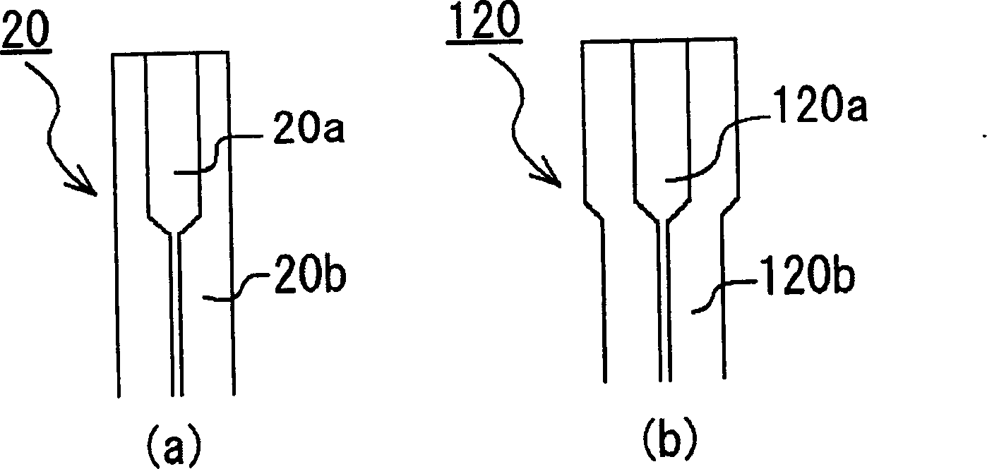
[0238] One end of the light guide 20 is connected to the light emitting part 12 of the excitation light source 10 , and the other end is connected to the output part 21 . As the light guide 20, for example, SI type 114 (μm: core diameter) / 125 (μm: cladding diameter) made of quartz is used.

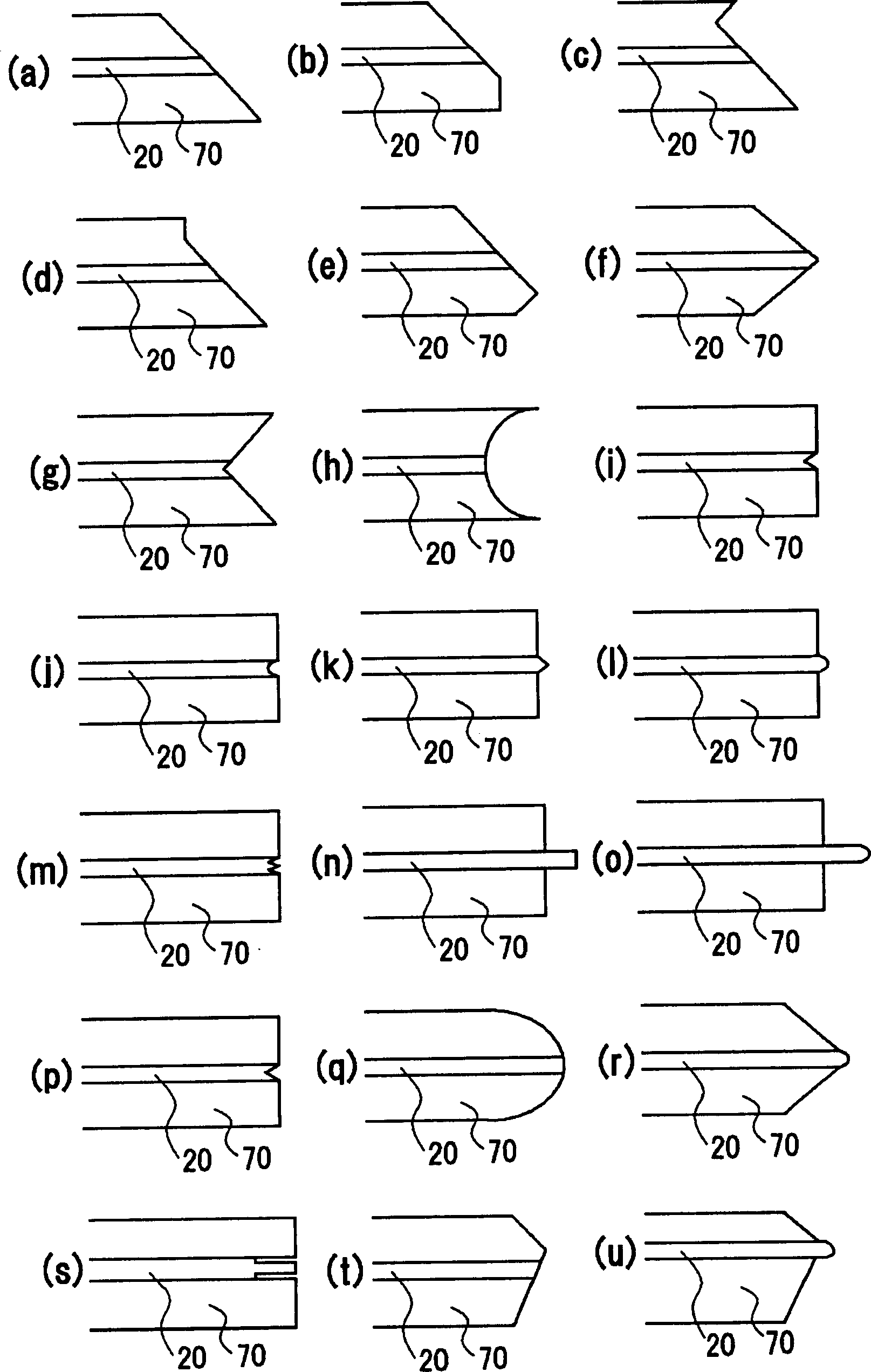
[0239] A ferrule made of SUS is attached to the front end of the light guide 20 .

[0240] In addition, the ITO film was arranged on the end face of the ferrule, that is, on the entire surface of the light exit surface of the light guide 20, w...

Embodiment 2

[0252] In the light-emitting device of this embodiment, LAG, BAM, YAG, SCA, SCESN, SESN, CESN and CaAlSiN are respectively used as fluorescent substances. 3 : Except for Eu, the light-emitting device was substantially the same as that of Example 1.

[0253] When these light-emitting devices were similarly evaluated, the results were approximately the same in terms of the relative intensity of light with respect to the light output and the lifetime.

Embodiment 3

[0255] In the light-emitting device of this example, as a fluorescent substance, except for mixing 10 g of Ca that emits blue light 10 (PO 4 ) 6 Cl 2 : Eu, mix 100 g of isopropanol, 20 g of alumina sol and 10 g of acetone, apply a voltage of 50 V, then dry, and electroplate the fluorescent substance, the light-emitting device is substantially the same as that of Example 1.

[0256] When these light-emitting devices were similarly evaluated, the results were approximately the same in terms of the relative intensity of light with respect to the light output and the lifetime.


PUM


Abstract

The present invention provides a light emitting device comprising: an excitation light source which radiates excitation light; a wavelength converting member which absorbs and converts the wavelength of at least part of the excitation light radiated from the excitation light source, and releases light with a predetermined wavelength band; a light guide for guiding the excitation light radiated from the excitation light source to the wavelength converting member, with one end at the excitation light source and the other end at the wavelength converting member, wherein the refractive index of the cross-sectional center region (core) is higher than that of the circumferential region (clad); and a thermally conductive transparent film which contacts with the wavelength converting member.

Description

technical field [0001] The present invention relates to a light-emitting device, in particular to a light-emitting device mainly comprising an excitation light source, a wavelength conversion member, and a light guide. Background technique [0002] Conventionally, in endoscope devices, fiberscopes, and the like, light capable of accurately reproducing color information with high brightness has been required. [0003] Therefore, as the light source, semiconductor light emitting elements such as light emitting diodes (LEDs) and laser diode elements (LDs) have been proposed instead of xenon lamps (for example, Japanese Patent Laid-Open Nos. 2002-95634 and 2003-515899). [0004] Semiconductor light-emitting element, small size, high power efficiency, emits light in bright colors, and does not have to worry about ball cutting, etc. In particular, since the luminous intensity of the semiconductor laser is much higher than that of the light emitting diode, a light source with high...

Claims


Application Information

Patent Timeline
IPC IPC(8): F21V8/00C09K11/00F21V7/22F21V9/02F21V9/08F21V9/16F21V17/00F21W107/00H01S5/00
CPCA61B1/0653
Inventor 滨敦智武市顺司杉山卓史林幸宏
Owner NICHIA CORP
Why Eureka
Try Eureka