Honeycomb structure

A honeycomb structure and honeycomb technology, applied in gas chambers, gas channels, gas treatment, etc., can solve problems such as reduction, crack bonding strength, and joint damage, and achieve the effect of not being easily damaged and maintaining bonding strength

Inactive Publication Date: 2006-12-27
IBIDEN CO LTD
View PDF6 Cites 19 Cited by
  • Summary
  • Abstract
  • Description
  • Claims
  • Application Information

AI Technical Summary

Problems solved by technology

[0018] When a honeycomb structure of such a shape is installed in an exhaust pipe of an internal combustion engine, there is a problem that since thermal stress tends to concentrate in the minor axis direction, the sealing material layer formed on the outer periphery as a coating layer and the honeycomb as an adhesive layer are bonded. The joints between the sealing material layers of the unit are susceptible to damage, resulting in cracks or loss of bond strength

Method used


Image

  • Honeycomb structure
  • Honeycomb structure
  • Honeycomb structure

Examples


Embodiment 1

[0138] Mix 40% by weight of γ-alumina particles (average particle diameter 2 μm), 10% by weight of silica-alumina fibers (average fiber diameter 10 μm, average fiber length 100 μm, aspect ratio 10) and 50% by weight of silica sol (solid concentration: 30% by weight), with respect to 100 parts by weight of the obtained mixture, after adding 6 parts by weight of methylcellulose, a small amount of plasticizer and a small amount of lubricant as an organic binder, they were mixed and kneaded to obtain a mixed composition .

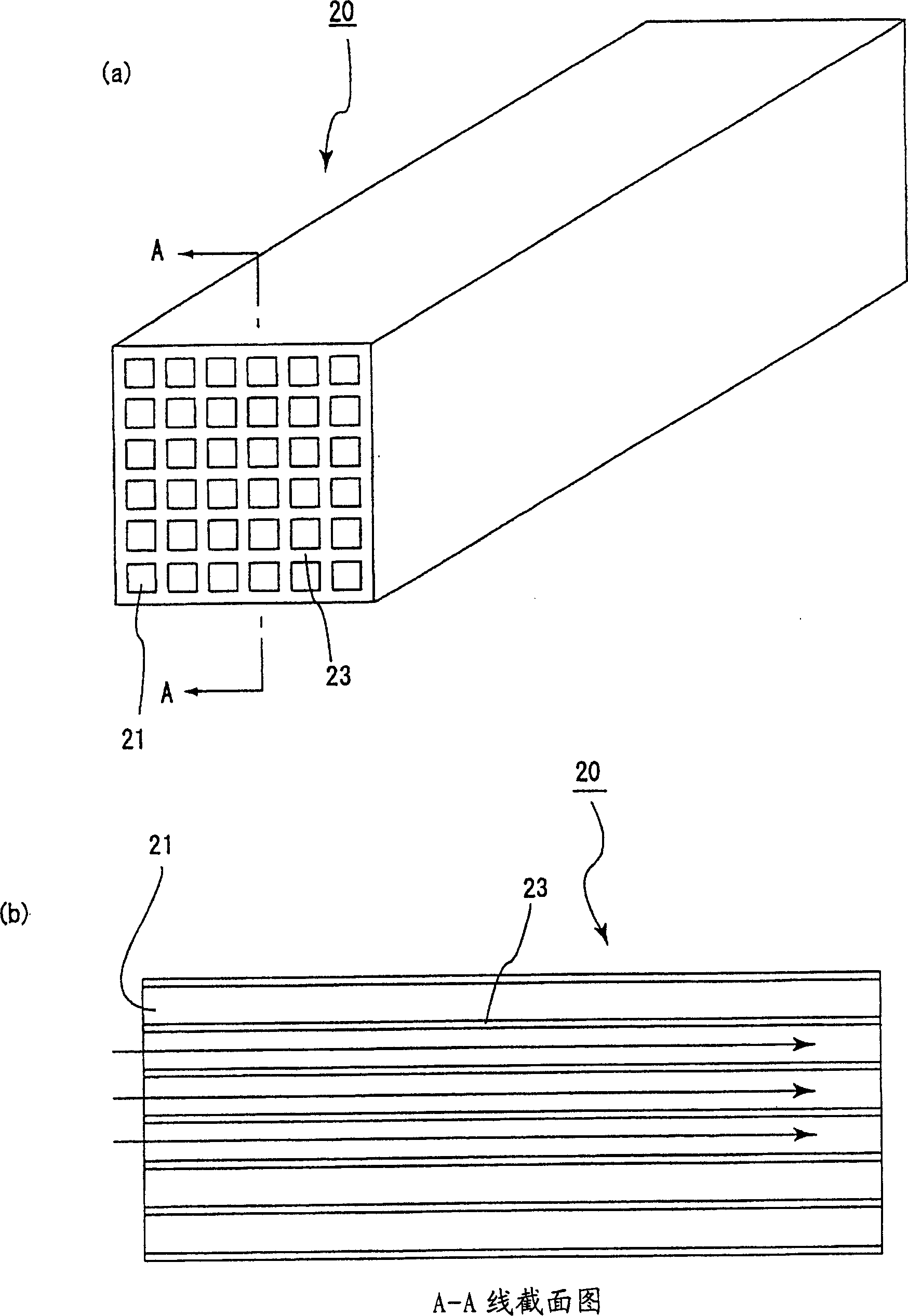
[0139] Then use the mixed composition to carry out extrusion molding to make the shape of the end face and figure 2 (a) A rough molded body having substantially the same end surface shape.

[0140] Next, dry the rough molded body with a microwave dryer to make a ceramic dry body, then degrease at 400°C for 2 hours, and then fire at 800°C for 2 hours to manufacture the honeycomb unit 20. The specific surface area is 42000m 2 / L, the size is 34.3mm×34.3mm×150...

Embodiment 2~7

[0150] (Examples 2-7, Comparative Examples 1-3)

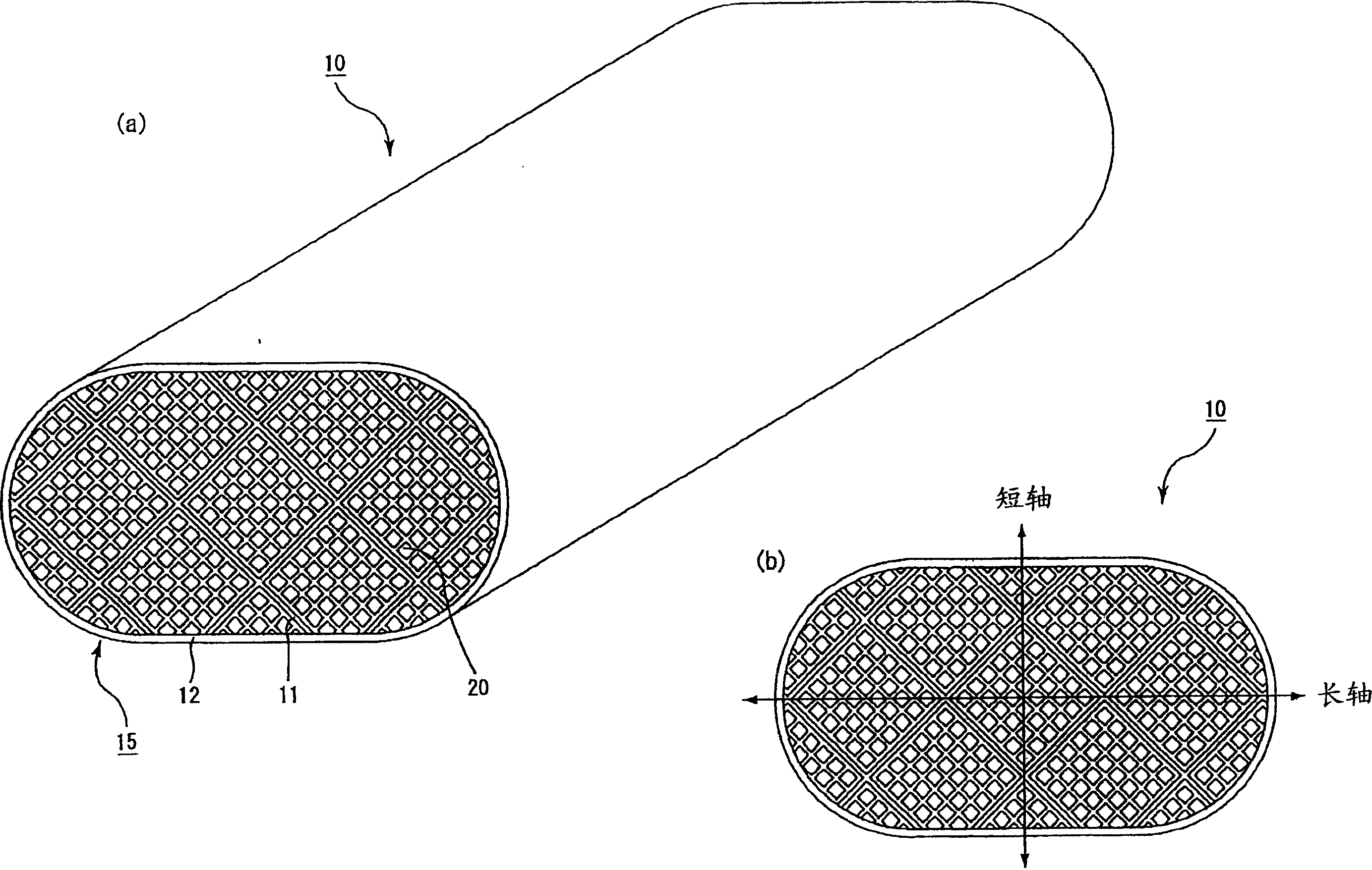
[0151] On the section perpendicular to the length direction, the angle formed by the sealing material layer (adhesive layer) between the honeycomb units and the major axis of the shape that constitutes the cross-sectional profile, and the value of the maximum cross-sectional area of ​​the honeycomb unit perpendicular to the length direction is as follows: Except as shown in Table 1, the honeycomb structure 10 was produced in the same manner as in Example 1.

Embodiment 8~14、 comparative example 4~6

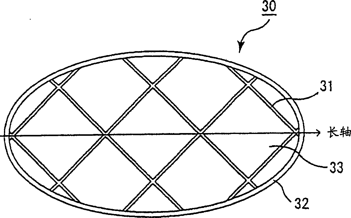
[0153] Set the end face profile to image 3 The ellipse shown, and the angle formed by the sealing material layer (adhesive layer) between the honeycomb units and the major axis of the shape constituting the cross-sectional profile on a section perpendicular to the length direction, and the honeycomb unit perpendicular to the length direction The value of the maximum cross-sectional area is shown in Table 1, and the honeycomb structure 30 was produced in the same manner as in Example 1 except that.


PUM

PropertyMeasurementUnit
areaaaaaaaaaaa
thicknessaaaaaaaaaa
thicknessaaaaaaaaaa

Abstract

An object of the present invention is to provide a flat-shaped honeycomb structured body in which sealing material layers are hardly damaged during use and in which adhesion strength can be maintained. The honeycomb structured body of the present invention is a honeycomb structured body including: a honeycomb block which has a flat-shaped cross section and has a structure in which plural honeycomb units are bonded to one another through sealing material layers, each unit including as amain component a porous ceramic and having in the longitudinal direction a number of cells placed in parallel with a cell wall therebetween; and a sealing material layer provided on an outer peripheral portion of the honeycomb block. Herein, each honeycomb unit contains inorganic fibers and/or whiskers in addition to inorganic particles, and the sealing material layer between the honeycomb units on the cross section perpendicular to the longitudinal direction is formed such that the direction thereof is diagonal to the major axis of a shape constituting the contour of the cross section.

Description

technical field [0001] The present invention relates to a honeycomb structure used as a catalyst carrier and the like. Background technique [0002] Conventionally, honeycomb catalysts generally used for automobile exhaust gas purification are produced by supporting a material with a large specific surface area such as activated alumina and a catalytic metal such as platinum on the surface of a cordierite honeycomb structure with a monolithic structure and low thermal expansion. Furthermore, in order to treat NOx under the condition of excess oxygen like lean-burn engines and diesel engines, alkaline earth metals such as Ba are also supported as NOx adsorbents. [0003] However, in order to improve the purification performance, it is necessary to increase the contact probability of the exhaust gas with the catalyst noble metal and with the NOx adsorbent. For this reason, it is necessary to further increase the specific surface area of ​​the carrier, reduce the size of the n...

Claims


Application Information

Patent Timeline
Patent Type & Authority Applications(China)
IPC IPC(8): B01J23/38B01J23/02C04B35/01C04B35/16C04B38/00B01D53/94
CPCB01D46/2459C04B2237/343F01N2330/30C04B2235/5296C04B38/0016C04B35/6316C04B2111/00793F01N2530/20C04B2237/064Y10T428/24149C04B2237/38F01N3/2828C04B2237/708C04B2235/5224C04B28/24B01D46/2451B01D46/2455F01N3/2853F01N2330/34C04B2235/526B01D2046/2496B01D2279/30C04B35/117C04B2235/5264F01N2530/24C04B37/005Y02W30/91B01D46/2498B01D46/2484B01D46/2482B01D46/2478C04B35/803C04B14/30C04B14/301C04B14/32C04B14/4625C04B14/4656C04B18/082C04B24/2623C04B24/383F01N3/022F01N3/02B01D46/2466B01D46/2486
Inventor 大野一茂国枝雅文尾久和丈
Owner IBIDEN CO LTD
Why Eureka
Try Eureka