Integrated hydrogen producing and storing process and apparatus

A hydrogen storage and electrochemical technology is applied in the field of integrated methods and devices for hydrogen production and hydrogen storage, which can solve the problems of adsorption capacity stability, adsorption pressure sensitivity, slow hydrogen absorption and desorption speed, and inability to meet the normal needs of gas filling stations.

Inactive Publication Date: 2007-06-27
SHANGHAI INST OF APPLIED PHYSICS - CHINESE ACAD OF SCI
View PDF1 Cites 6 Cited by
  • Summary
  • Abstract
  • Description
  • Claims
  • Application Information

AI Technical Summary

Problems solved by technology

[0006] A fatal flaw of previously studied carbon nanomaterials is: the slow rate of hydrogen absorption and desorption
This is like charging a battery and cannot meet the normal needs of a gas station
The hydrogen storage of carbon nanomaterials also has the following problems: the stability of the adsorption capacity and the sensitivity of the adsorption pressure

Method used


Image

  • Integrated hydrogen producing and storing process and apparatus
  • Integrated hydrogen producing and storing process and apparatus
  • Integrated hydrogen producing and storing process and apparatus

Examples


Embodiment 1

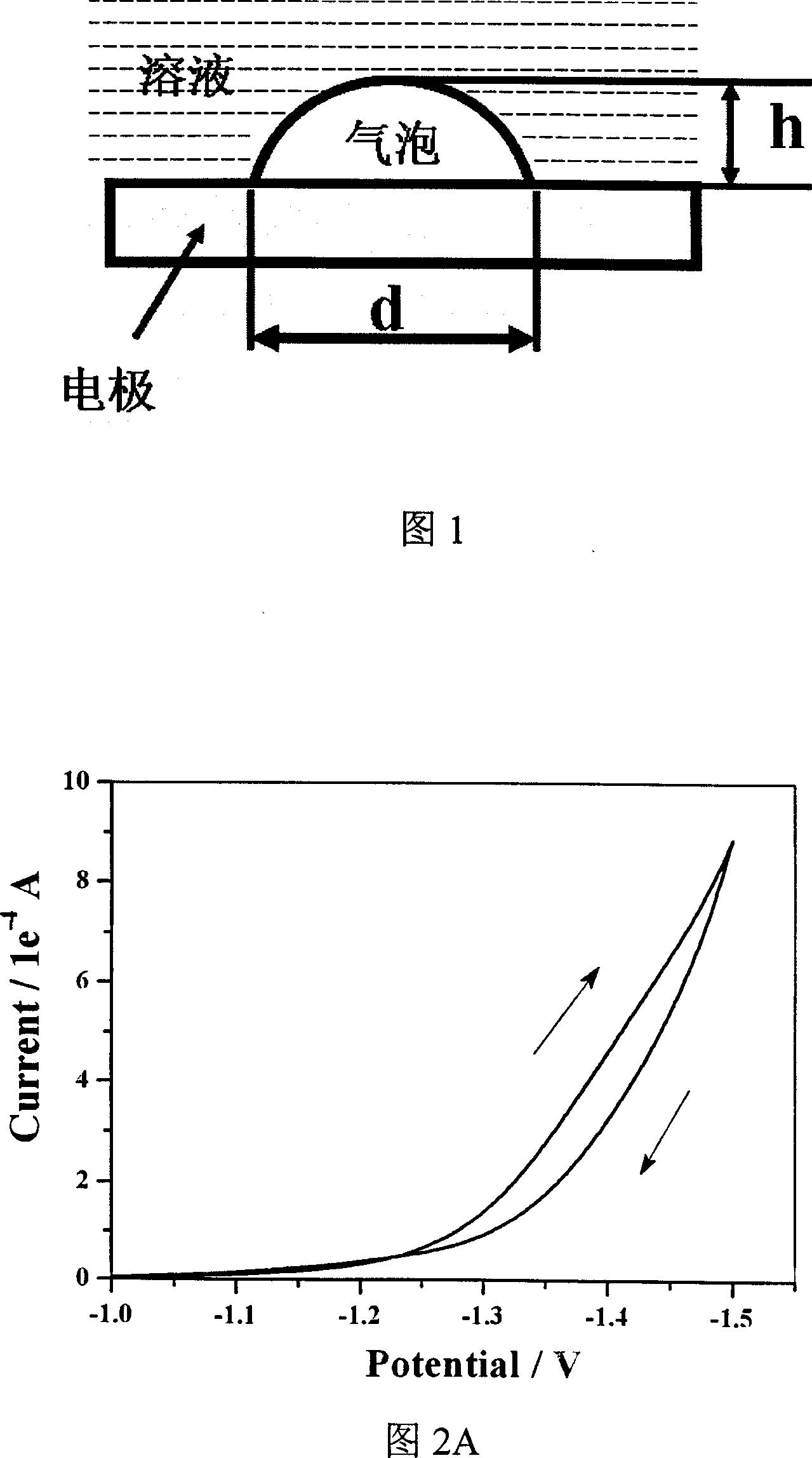
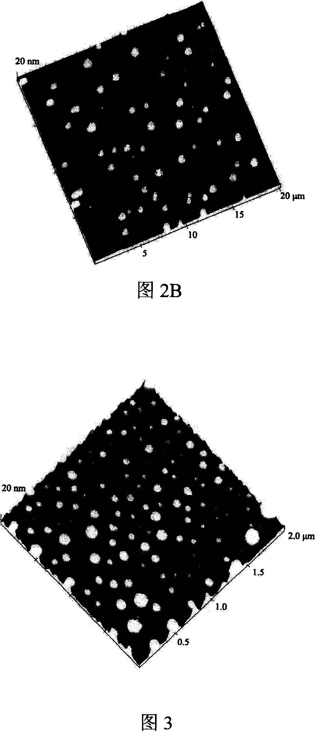
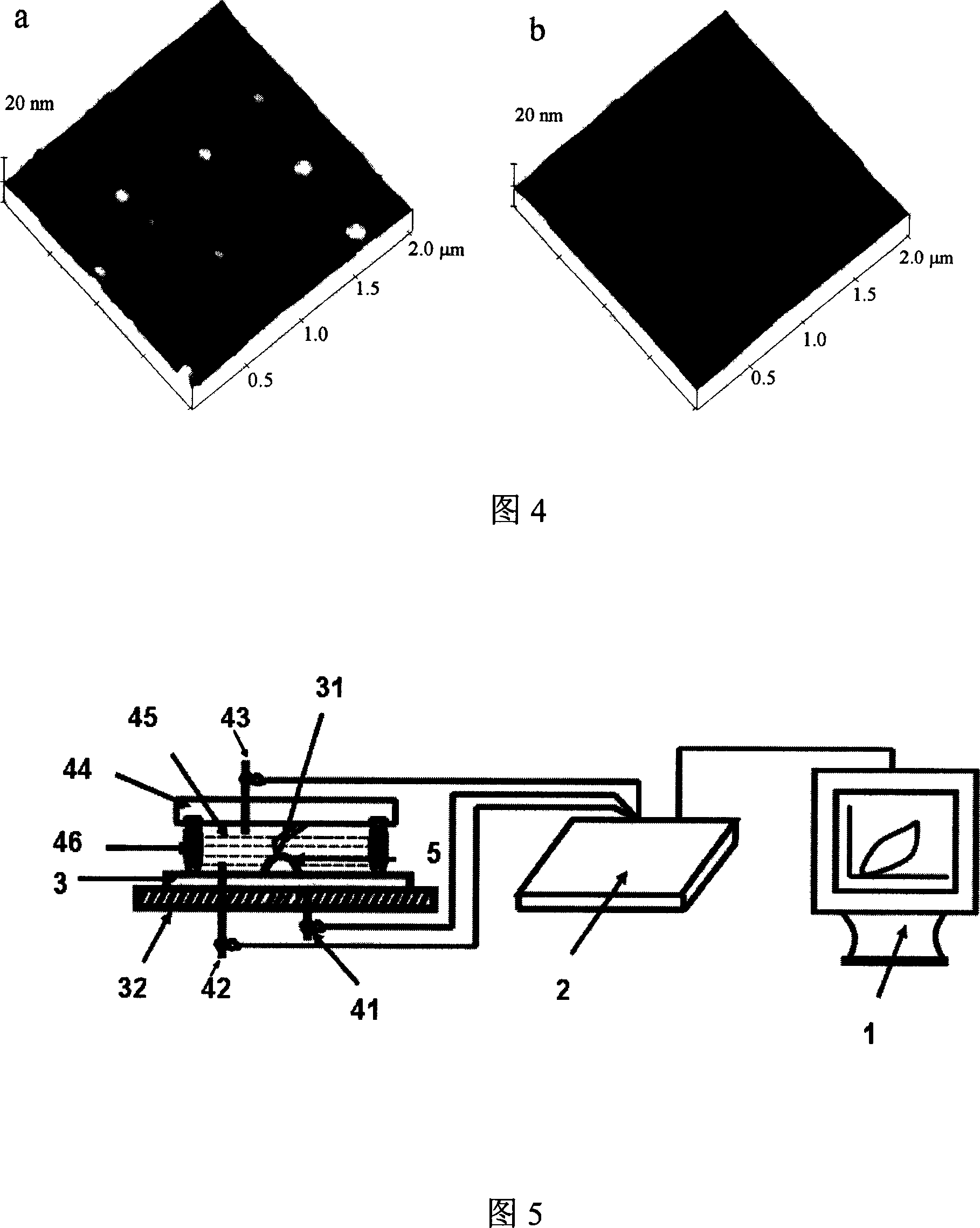
[0050] As shown in Fig. 5, a piece of 12mm×12mm high-order pyrolytic graphite 3 is used as a hydrogen storage device and AFM observation substrate to be glued on the AFM special magnet sheet 32 ​​with conductive silver glue. Before use, use double-sided tape to peel off the graphite surface layer, and the magnet sheet with graphite 3 attached is attached to the stage (not shown) of the head of the atomic force microscope. Adjust the head position, and fix the AFM tip 31 on the AFM special liquid tank (liquid tank) 4 so that the tip 31 is about 40 μm away from the surface of the graphite substrate 3, and an O-ring 46 is fixed between the liquid tank 4 and the graphite substrate 3 to seal , The liquid tank 4 is also provided with a drain pipe (not shown). Quickly inject the pre-degassed 0.001-1.0mol / L diluted sulfuric acid electrolyte solution 45. Use an atomic force microscope to observe the morphology of the graphite surface before applying voltage as a control. The working electr...

Embodiment 2

[0058] The device and operation steps are the same as in Example 1, but using 0.001-1.0 mol / L potassium hydroxide solution as the electrolyte, the applied voltage range is -1.0V to -2.0V, and the time is 1-120 seconds. The height range of the obtained nanobubbles is 2-100nm.

[0059] The size of nanobubbles generated in 0.001-1.0 mol / L sodium nitrate, potassium nitrate, barium sulfate and other solutions is similar to that of sulfuric acid and potassium hydroxide solutions, so we will not give examples here.

Embodiment 3

[0061] As shown in Figure 6, the bottom of the electrochemical cell 4 is equipped with a hydrogen storage device high-order pyrolytic graphite 3, the graphite 3 is connected to the working electrode wire 41, and the bottom of the electrochemical cell 4 is also provided with a drain switch that can be opened and closed. 7. The reference electrode is placed in the above-mentioned electrolyte solution 45 through the side wall of the electrochemical cell 4. The top surface of the electrochemical cell is provided with an outlet 6 for the discharge of oxygen or hydrogen, and the counter electrode 43 is placed in the electrolyte solution through the outlet 6 45 in.

[0062] In the same way, the three-electrode clip of the electrochemical instrument 2 connected to the computer 1 is clamped to the corresponding electrodes to form the integrated hydrogen production and storage device of the present invention.

[0063] Same as Example 1 or 2, after a certain negative pressure is applied to t...


PUM

PropertyMeasurementUnit
densityaaaaaaaaaa
elasticityaaaaaaaaaa
thicknessaaaaaaaaaa

Abstract

The integrated hydrogen producing and storing process is one electrochemical process at negative voltage, of reaction period of 1-120 sec, and with ordered pyrolytic graphite as work electrode to produce and adsorb nanometer hydrogen bubble. The corresponding hydrogen producing and storing apparatus is also disclosed. The integrated hydrogen producing and storing process has high repeatability, normal pressure and normal temperature operation, no pollution and simple hydrogen release; and the apparatus has low cost, high safety, fast hydrogen storing and releasing speed and other advantages.

Description

Technical field [0001] The invention relates to the field of manufacturing and storing hydrogen energy, in particular to an integrated method and device for hydrogen production and storage. Background technique [0002] With the depletion of traditional energy oil and coal, the combustion products of oil and coal CO 2 And SO 2 The greenhouse effect and acid rain are produced respectively, making mankind face severe challenges from energy, resource and environmental crises. Mankind increasingly needs clean new energy. Hydrogen energy has aroused widespread interest due to its renewable advantages and abundant resources, and hydrogen does not cause environmental pollution and is a very ideal and clean energy. Hydrogen storage is the key to the use of hydrogen energy, and it is also a worldwide problem. Many countries have invested heavily in research. The United States allocated 1.2 billion US dollars in 2003 for research on hydrogen energy (preparation and storage). There are two ...

Claims


Application Information

Patent Timeline
Patent Type & Authority Applications(China)
IPC IPC(8): C25B1/04C25B11/12B01J20/20F17C11/00
CPCB82Y30/00Y02E60/328Y02E60/366Y02E60/321Y02E60/325C01B3/001C01B3/0021Y02E60/32Y02E60/36
Inventor 张立娟胡钧方海平樊春海张益沈广霞
Owner SHANGHAI INST OF APPLIED PHYSICS - CHINESE ACAD OF SCI
Why Eureka
Try Eureka