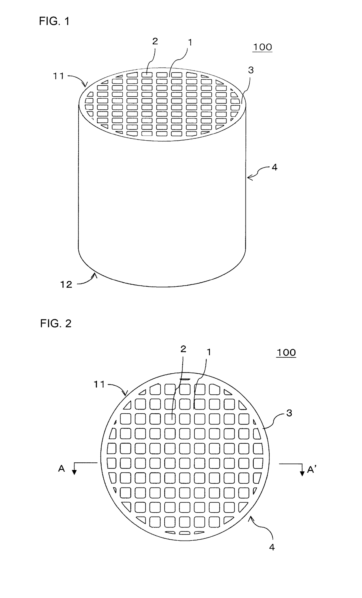
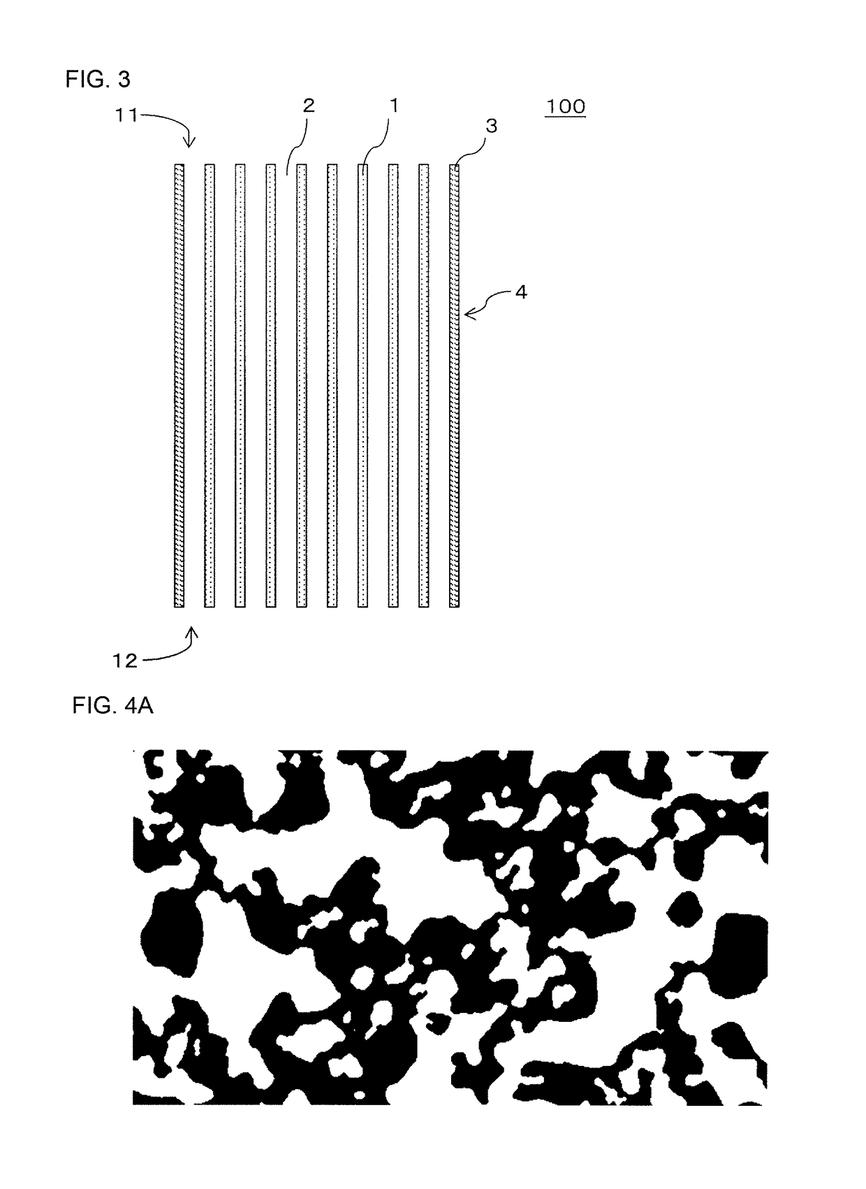
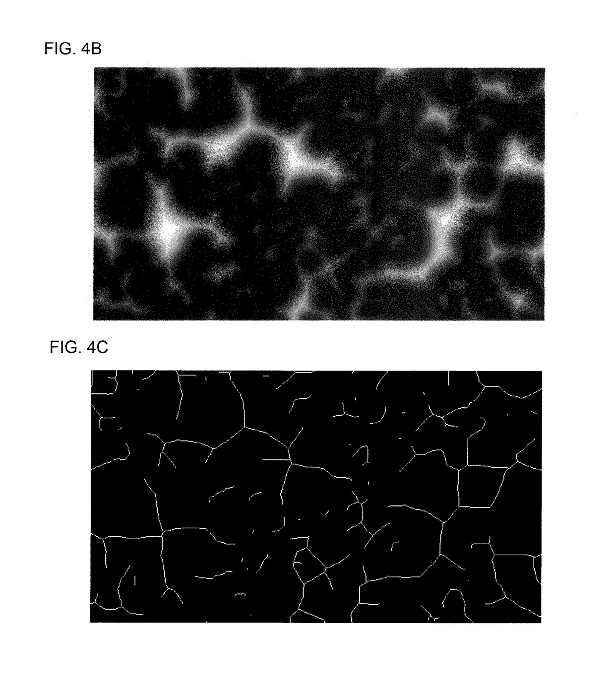
Honeycomb structure

a honeycomb and structure technology, applied in the field of honeycomb structure, can solve the problems of reducing the strength of the honeycomb structure, difficult to lower the porosity, and the thermal diffusivity of the obtained honeycomb structure, and achieves the effect of suppressing local excessive temperature rise, high thermal diffusivity, and low heat capacity

Active Publication Date: 2019-03-19
NGK INSULATORS LTD
View PDF12 Cites 6 Cited by
  • Summary
  • Abstract
  • Description
  • Claims
  • Application Information

AI Technical Summary

Benefits of technology

[0013]Herein, in order to control the heat capacity or the thermal diffusivity of a porous sintered body containing silicon as a main component, the porosity thereof has to be controlled. A porous sintered body containing silicon as a main component, however, has a problem that sintering due to surface diffusion occurs preferentially over sintering due to volume diffusion, and so it is difficult to lower the porosity. The honeycomb structure described in Patent Document 1 includes metals such as Al, Fe, Ni, Ti, B, P, and Ca as sintering aid so as to obtain a porous sintered body containing silicon as a main component. Such sintering aid has a melting point lower than that of silicon, and so the formed body obtained by extrusion of a forming raw material has a low melting point locally at the part containing such sintering aid. This means that, when such a formed body is sintered, sintering is progressed locally at the part containing the sintering aid, which leads to a problem that the obtained honeycomb structure has lower thermal diffusivity. In addition, there is another problem that locally progressed sintering reduces strength of the honeycomb structure and reduces trapping performance of the honeycomb structure when it is used as a filter.
[0016]In view of such problems, the present invention aims to provide a honeycomb structure with low heat capacity and high thermal diffusivity and that follows the ambient temperature change rapidly.
[0036]The honeycomb structure of the present invention includes a pillar-shaped honeycomb structure body having a porous partition wall. The honeycomb structure body includes a plurality of cells defined by the partition wall so as to extend from a first end face to a second end face of the honeycomb structure body. The partition wall is formed by a porous body including a silicon phase as a main phase, and the silicon phase as the main phase has content of each of metals other than silicon and metals making up silicide that is 0.3 part by mass or less with respect to 100 parts by mass of silicon. With this configuration, the honeycomb structure of the present invention has an advantageous effect of low heat capacity and high thermal diffusivity and of following the ambient temperature change rapidly. Therefore, when the honeycomb structure of the present invention is used as a DPF, for example, the temperature-rising property during regeneration of the DPF can be improved, and its locally excessive temperature rising can be suppressed. When the honeycomb structure of the present invention is used as a GPF, the temperature-rising property during exhaust gas flow can be improved, and the temperature of the GPF is allowed to rise quickly and uniformly. When the honeycomb structure of the present invention is used as various types of catalyst carriers as well, the temperature-rising property of the catalyst carrier can be improved, and the temperature of the catalyst carrier is allowed to rise quickly and uniformly.

Problems solved by technology

A porous sintered body containing silicon as a main component, however, has a problem that sintering due to surface diffusion occurs preferentially over sintering due to volume diffusion, and so it is difficult to lower the porosity.
This means that, when such a formed body is sintered, sintering is progressed locally at the part containing the sintering aid, which leads to a problem that the obtained honeycomb structure has lower thermal diffusivity.
In addition, there is another problem that locally progressed sintering reduces strength of the honeycomb structure and reduces trapping performance of the honeycomb structure when it is used as a filter.
The honeycomb structure described in Patent Document 2 includes silicon carbide particles mainly as the refractory particles, and so has a problem that the heat capacity of the honeycomb structure is large and the temperature-rising property is poor.
That is, the honeycomb structure described in Patent Document 2 has the difficulty to follow the ambient temperature change rapidly.
The honeycomb structure described in Patent Document 3 also has a problem of large heat capacity and poor temperature-rising property similarly to the honeycomb structure described in Patent Document 2 because it includes silicon carbide particles as the aggregate.

Method used


Image

  • Honeycomb structure
  • Honeycomb structure
  • Honeycomb structure

Examples


example 1

[0110]In Example 1, silicon raw material powder A was used as the silicon raw material powder. For the forming raw material, 5,000 g of silicon raw material powder A and 350 g of methylcellulose as binder as well as appropriate amount of water added were prepared.

[0111]Next, the obtained forming raw material was kneaded by a kneader, and then was pugged by a vacuum pugmill to form a kneaded material. Next, the obtained kneaded material was extruded to prepare a honeycomb formed body. The honeycomb formed body was such that the partition wall thereof after firing had the thickness of 300 μm, and the cell density of 46.5 cells / cm2. The honeycomb structure body of the honeycomb formed body was a quadrangular pillar shape, in which the length of one side of the end face was 35 mm after firing. Next, the honeycomb formed body was dried to obtain a honeycomb dried body. Drying included microwave drying, followed by hot air drying at 80° C.

[0112]Next, the obtained honeycomb dried body was ...

example 2

[0134]In Example 2, silicon raw material powder A was used as the silicon raw material powder. For the forming raw material, 5,000 g of silicon raw material powder A, 50 g of cordierite powder with the average particle diameter of 2 μm, and 350 g of methylcellulose as binder as well as appropriate amount of water added were prepared. Then a honeycomb structure was obtained using the obtained forming raw material similarly to Example 1 other than that the temperature condition for firing was changed as follows. Firing in Example 2 was performed, including temperature rising to 1,200° C. in 2 hours firstly, followed by temperature rising to 1,400° C. in 20 hours and then the temperature was kept at 1,400° C. for 2 hours. Firing was performed in the Ar atmosphere. Hereinafter this temperature condition for firing is called “firing condition b”.

example 3

[0135]In Example 3, a honeycomb structure was obtained similarly to Example 2 other than that the amount of cordierite powder to be added to the forming raw material was changed to 221 g.


PUM

PropertyMeasurementUnit
particle diameteraaaaaaaaaa
thicknessaaaaaaaaaa
lengthaaaaaaaaaa

Abstract

A honeycomb structure includes a pillar-shaped honeycomb structure body having a porous partition wall. The honeycomb structure body includes a plurality of cells defined by the partition wall so as to extend from a first end face to a second end face of the honeycomb structure body, the partition wall is formed by a porous body including a silicon phase as a main phase, and the silicon phase as the main phase has content of each of metals other than silicon and metals making up silicide that is 0.3 part by mass or less with respect to 100 parts by mass of silicon.

Description

[0001]The present application is an application based on JP 2015-058562 filed on Mar. 20, 2015 with the Japan Patent Office, the entire contents of which are incorporated herein by reference.BACKGROUND OF THE INVENTION[0002]Field of the Invention[0003]The present invention relates to honeycomb structures. More particularly the present invention relates to a honeycomb structure with low heat capacity and high thermal diffusivity and that follows the ambient temperature change rapidly.[0004]Description of the Related Art[0005]Exhaust gas emitted from an internal combustion engine, such as a diesel engine and a gasoline engine, or various types of combustion devices contain a lot of particulate substances (hereinafter called “particulate matter” or “PM” as well) mainly containing soot. If this PM is discharged directly to the air, environment pollution will be caused, and so an exhaust system for exhaust gas includes a particulate filter to trap PM. For instance, examples of a particul...

Claims


Application Information

Patent Timeline
Patent Type & Authority Patents(United States)
IPC IPC(8): B01D46/24C04B35/515C04B38/00B01J35/04F01N3/022F01N3/027C04B111/00
CPCB01D46/2429B01D46/2474B01J35/04C04B35/515C04B38/0006C04B38/0009C04B38/0016F01N3/0222F01N3/0275C04B38/0054C04B38/0074C04B2235/85C04B2235/80C04B2235/428B01D2046/2433B01D2046/2437C04B2111/0081C04B2111/00793C04B2235/3206C04B2235/3217C04B2235/3418B01D46/24492B01D46/24491B01D46/2482B01D46/2476B01D46/2478
Inventor KIKUCHI, YOSHIOISHIKAWA, MASAKI
Owner NGK INSULATORS LTD
Why Eureka
Try Eureka