

Anode slurry and method for preparing the same
a technology of anode slurry and anode material, which is applied in the manufacture of electrodes, cell components, electrochemical generators, etc., can solve the problems of large volume change greater than 300%, cracks or even pulverization near the surface, and limit the improvement of energy density, so as to prolong improve the initial coulombic efficiency of the anode material. , the effect of prolonging the life of the battery
- Summary
- Abstract
- Description
- Claims
- Application Information
AI Technical Summary
Benefits of technology
Problems solved by technology
Method used
Image

Examples
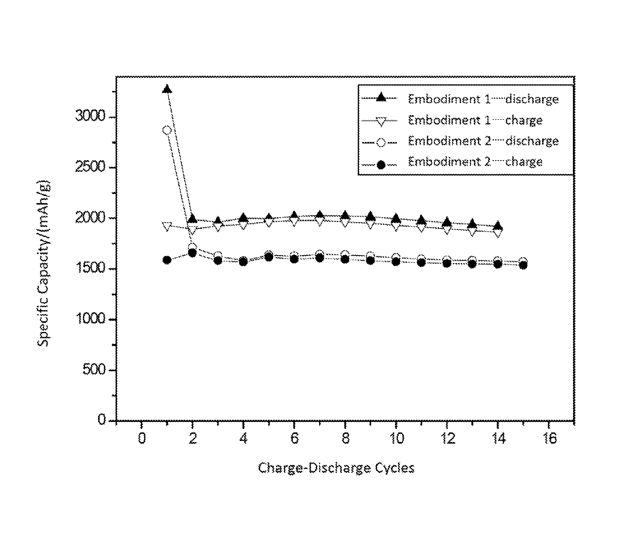
embodiment 1
[0033]Mixing 10 g nano-silicon powder, 1 g Ketjenblack conductive agent (EC600JD) and 9 g acrylic acid with 30 g water, wherein the average diameter D50 of the nano-silicon powder being 200 nm. After stirring and ultrasonic dispersing treatment, a 1st mixture is obtained. Next, dissolving 1.5 g sodium persulfate (abbr. as SPS) into 10 g water to obtain a 2nd mixture, wherein the SPS acting as an initiator. Finally, adding the 2nd mixture into the 1st mixture, stirring at 70° C. for 3 hours, and yielding anode slurry of the lithium batteries.
embodiment 2
[0034]Mixing 10 g nano-silicon powder, 1 g Ketjenblack conductive agent (EC600JD) and 9 g acrylic acid with 30 g water, wherein the D50 of the nano-silicon powder being 100 nm. After stirring and ultrasonic dispersing treatment, a 1st mixture is obtained. Next, dissolving 1 g ammonium persulfate (abbr. as APS) into 10 g water to obtain a 2nd mixture, wherein the SPS acting as initiator. Finally, adding the 2nd mixture into the 1st mixture, stirring at 75° C. for 4 hours, and yielding anode slurry of lithium batteries.
embodiment 3
[0035]Mixing 5 g nano-silicon powder, 0.5 g Super P conductive agent and 7 g acrylic acid with 40 g water, after stirring and ultrasonic dispersing treatment, a 1st mixture is obtained. Next, dissolving 1 g APS into 10 g water to obtain a 2nd mixture, wherein the APS acting as initiator. Finally, adding the 2nd mixture into the 1st mixture, stirring at 100° C. for 2 hours, and yielding anode slurry of lithium batteries.
PUM
| Property | Measurement | Unit |
|---|---|---|
| particle diameter | aaaaa | aaaaa |
| particle diameter | aaaaa | aaaaa |
| particle diameter | aaaaa | aaaaa |
Abstract
Description
Claims
Application Information