Method and apparatus for lining the cathode of the electrolytic cell

Active Publication Date: 2019-12-10
UNITED COMPANY RUSAL ENG & TECH CENT
View PDF8 Cites 0 Cited by
  • Summary
  • Abstract
  • Description
  • Claims
  • Application Information

AI Technical Summary

Benefits of technology

The patent proposes a technical solution to improve the production of aluminum by reducing the apparent porosity of lining layers and increasing the reliability of the apparatus. This is achieved by slowing down the rate of penetration of molten fluoride salts and aggressive gaseous components into the cathode thermal insulation through the barrier layer, and improving cell performance (decreasing power consumption and increasing operation life of the cell). The apparatus may be designed with elastic elements to prevent vibration transfer to the electric motor and other elements, increasing the reliability and durability of the device. The experience of using the apparatus has shown higher degrees of compaction of the upper layers of the lining material.

Problems solved by technology

Thus, due to a significantly lower density of the β-alumina reaction product, volumetric changes occur in the lining, causing vertical stresses in the bottom and its possible destruction.
An increase in melt viscosity due to the presence of albite in the reaction zone between the aluminosilicate refractory lining and molten cryolite reduces the likelihood of the penetration of fluoride salts into the lower insulating layers of the pit.
At a very high SiO2 content (72%), due to insufficient Al2O3, nepheline formation will be difficult.
In addition, the presence of a temperature gradient in the direction of the penetration along with the increase in melt viscosity due to the formation of albite, will also slow down the penetration process.
The refractory mortar used for sealing seams (on which brickwork mortar is based) is vulnerable to fluoride salts and aggressive gases due to its high porosity.
In addition, water used for preparing brickwork mortar causes, at low temperatures, problems with the assembly of the electrolytic cell and has a negative impact on the durability of thermal insulation materials in the cell's cathode.
Test results, however, did not confirm the viability of this lining method because a high porosity of the un-compacted layer led to a continuous supply of gaseous and liquid components to the thermal insulation.
However, an evaluation of static formation results shows that it does not provide for the desired structure of a lining material: low porosity and small-sized pores.
This leads to a certain increase in packing density but the resulting barrier layer still has a relatively high porosity (up to 25%) and, moreover, it has wave-like defects on the surface.
The disadvantage of this method is material segregation and particle separation along the layer's height; hence, there is a low degree of resistance to penetration of fluoride salts.
This leads to high rates of chemical reactions, which reduces the operation life of the cell.
However, the use of hot ramming paste is environmentally hazardous, and the transition to cold ramming paste and a decrease in cryolite ratio reduces the operation life of the cell.
However, when using such a device, both compaction and de-compaction of the mix occur at the same time; as a result, dusting of the material being compacted is observed.
This leads to a certain increase in packing density but the resulting barrier layer still has a relatively high porosity (up to 25%) and, moreover, it has wave-like defects on the surface.
The main disadvantage of this method is multiple passes (trips) of the vibratory platform over the surface of the barrier material (due to a small size of the platform.)
However, the most significant disadvantage is that the operation of the vibratory platform is primarily based on the dynamic method of formation (under non-optimum frequency and weight characteristics.)
The use of relatively thin glass fiber laminate sheets or MDF, not having sufficient hardness, results in an un-even surface; the surface of the barrier material after lining, as in the case of using vibratory compactors, is wave-like.
This lining method does not meet the requirements regarding producing a high-quality, large depth and low bulk density barrier layer.
The main disadvantage of the prototype apparatus is that the compacted material is pushed out right before the unit for static treatment, when forming a barrier layer of great depth and low bulk density.
Moreover, the lack of such design elements that damp the horizontal component of vibration causes technical problems, when using, as a source of oscillations, vibratory exciters with a circular driving force or vibratory exciters with a directional driving force mounted on the vibratory unit at an acute angle to the treated surface (due to the transmission of vibration of the whole structure.)
When using such oscillation sources, the electric motors of the unit for static treatment and other elements of the apparatus undergo vibration, which can lead to their failure, and, hence, reduce operational reliability.

Method used


Image

  • Method and apparatus for lining the cathode of the electrolytic cell
  • Method and apparatus for lining the cathode of the electrolytic cell
  • Method and apparatus for lining the cathode of the electrolytic cell

Examples


Embodiment Construction

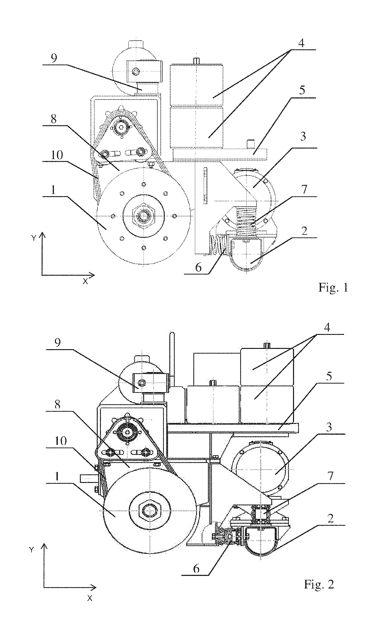
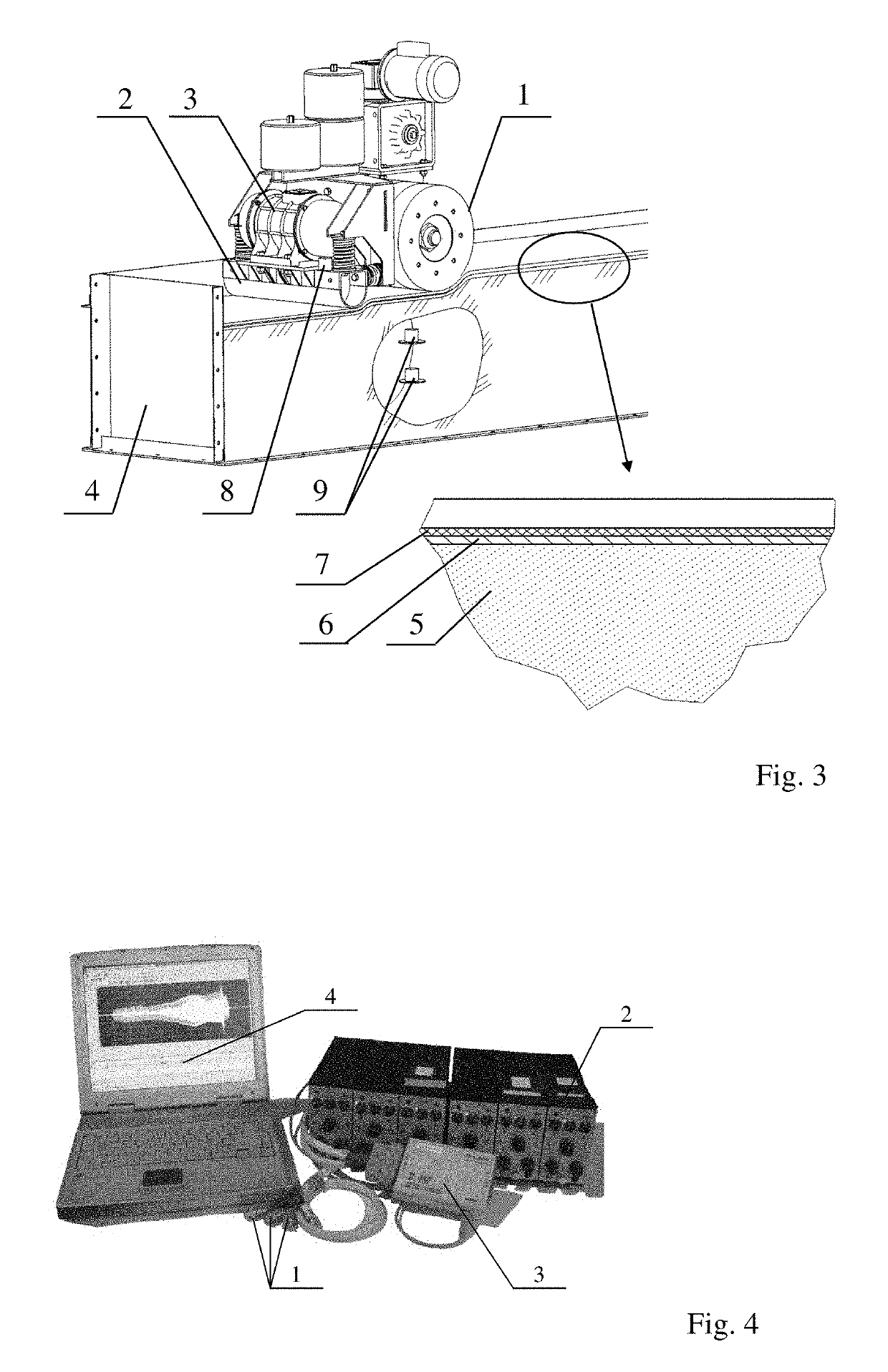
[0059]The essence of this technical solution is illustrated by an example of specific design and drawings. FIG. 1 shows an apparatus for forming seamless lining layers in electrolytic cells (side view) with elastic elements made of metal springs; and FIG. 2 shows an apparatus for forming seamless lining layers in electrolytic cells (side view) with elastic elements made of rubber.

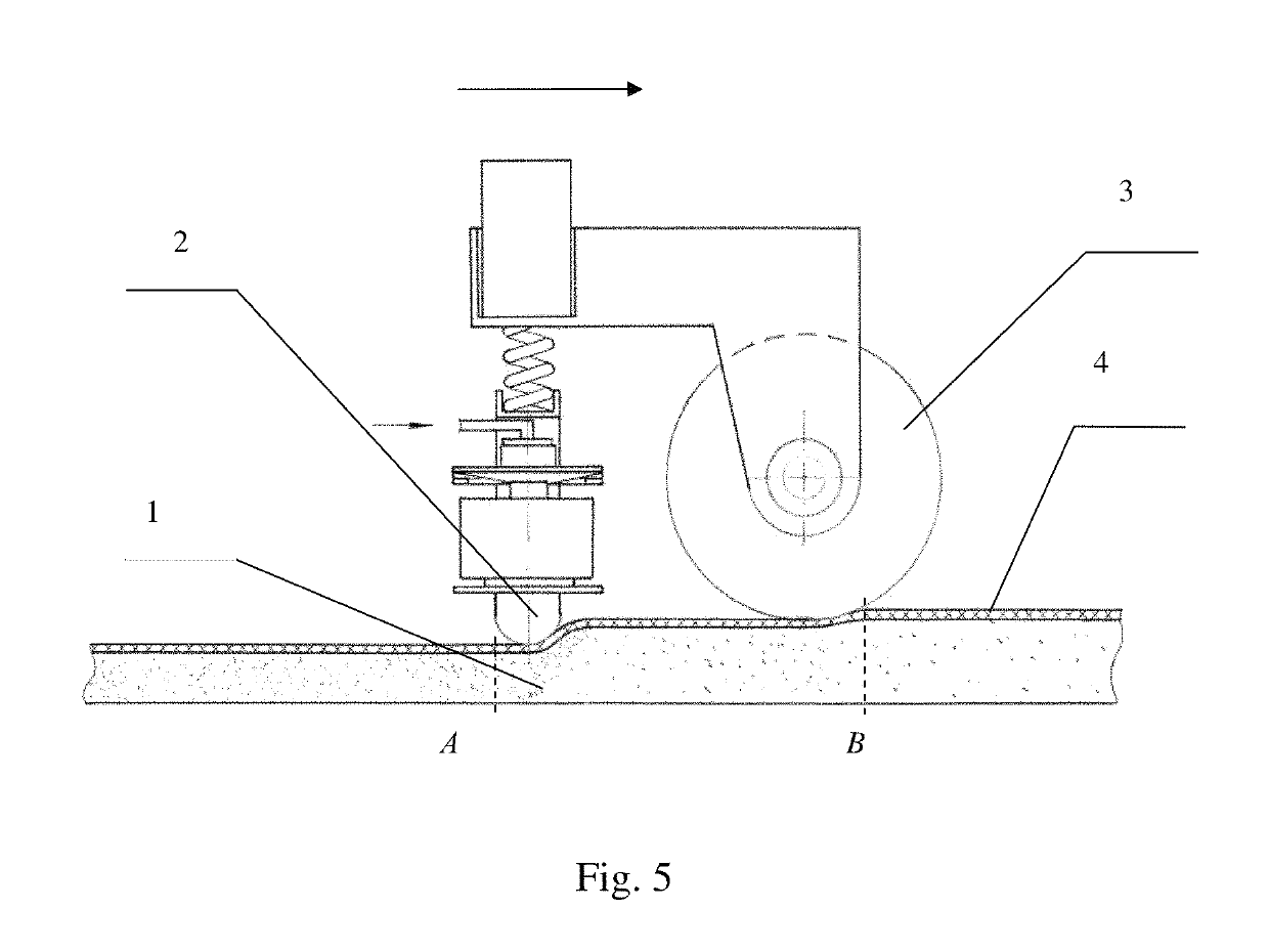
[0060]The apparatus for forming seamless lining layers in electrolytic cells consists of driving disks 1, which form a drive unit for static compaction (in the form of a roller), vibratory unit 2 with vibrator 3, weights 4 located on load platform 5, which is connected to vibratory unit 2 by means of elastic elements 6 and 7 (made of metal springs in FIG. 1 and rubber in FIG. 2), 5 which combine the vibratory unit and the static treatment unit into a compaction device by means of rocker arm 8, including the ability to freely move the vibratory unit along the horizontal (X) and vertical (Y) axes (anchor) of ...


PUM

PropertyMeasurementUnit
Weightaaaaaaaaaa
Forceaaaaaaaaaa
Accelerationaaaaaaaaaa

Abstract

The invention relates to method and apparatus for lining the cathode of the electrolytic cell. The method comprises filling the cell's shell with powder material, leveling it with a rack, covering the fill material with a dust-proof film, and compaction. Compaction is performed in two stages: preliminary static and final dynamic treatment by consequent movement of static and dynamic work tools of compaction along the longitudinal axis of the cathode of the electrolytic cell through a cushion, which is made of at least 2 layers: a lower layer, which prevents pushing powder material forward in the direction of travel, and an upper layer, which provides for a coupling between the cushion and the static work tool. Static treatment unit of the apparatus is designed in the form of a roller with a drive, connected to a dynamic treatment unit with a vibratory exciter by means of elastic elements.

Description

CROSS REFERENCE TO RELATED APPLICATION[0001]This application is a divisional of and claims priority to U.S. patent application Ser. No. 14 / 437,388 filed Oct. 25, 2012, which is a U.S. National Phase under 35 U.S.C. § 371 of International Application PCT / RU2012 / 000875, filed on Oct. 25, 2012. All publications, patents, patent applications, databases and other references cited in this application, all related applications referenced herein, and all references cited therein, are incorporated by reference in their entirety as if restated here in full and as if each individual publication, patent, patent application, database or other reference were specifically and individually indicated to be incorporated by reference.FIELD OF INVENTION[0002]The proposed technical solution relates to the field of non-ferrous metallurgy and, in particular, to using unshaped materials for lining the cathode of the electrolytic cell in primary aluminum production.BACKGROUND[0003]The cathode of the electro...

Claims


Application Information

Patent Timeline
IPC IPC(8): C25C3/08B05C11/02B05C11/08
CPCC25C3/08B05C11/08B05C11/025
Inventor PROSHKIN, ALEKSANDR VLADIMIROVICHLEVENSON, SAMUIL YAKOVLEVICHPINGIN, VITALIY VALER'EVICHMOROZOV, ALEKSEY VASIL'EVICH
Owner UNITED COMPANY RUSAL ENG & TECH CENT
Why Eureka
Try Eureka