
Ultraviolet light-emitting diode and electric apparatus provided with the same

a technology of ultra-violet light and electric apparatus, which is applied in the direction of electrical apparatus, basic electric elements, semiconductor devices, etc., can solve the problems of difficult improvement of carrier injection efficiency, increased hole concentration, and still have room for improvement in luminous efficacy, so as to improve the performance of electric apparatus, improve the external quantum efficiency, and improve the effect of carrier injection efficiency

Active Publication Date: 2020-03-17
RIKEN +1
View PDF10 Cites 0 Cited by
  • Summary
  • Abstract
  • Description
  • Claims
  • Application Information

AI Technical Summary

Benefits of technology

The present invention aims to improve the efficiency of UV LEDs, which can be used in electric devices. By improving the way in which electric current is injected into the LED, the invention helps to make them more effective. This will contribute to the performance of devices that use UV LEDs.

Problems solved by technology

One of technical challenges confronted by deep ultraviolet LEDs is that their luminous efficacy still has room for improvement.
Such a deep ultraviolet LED, however, has carrier injection efficiency which is difficult to improve.
This problem arises partly because an Mg acceptor exhibits too high activation energy and too intense self-compensation effect in a p-type layer to increase the hole concentration easily.

Method used


Image

  • Ultraviolet light-emitting diode and electric apparatus provided with the same
  • Ultraviolet light-emitting diode and electric apparatus provided with the same
  • Ultraviolet light-emitting diode and electric apparatus provided with the same

Examples


first example

6-1. First Example

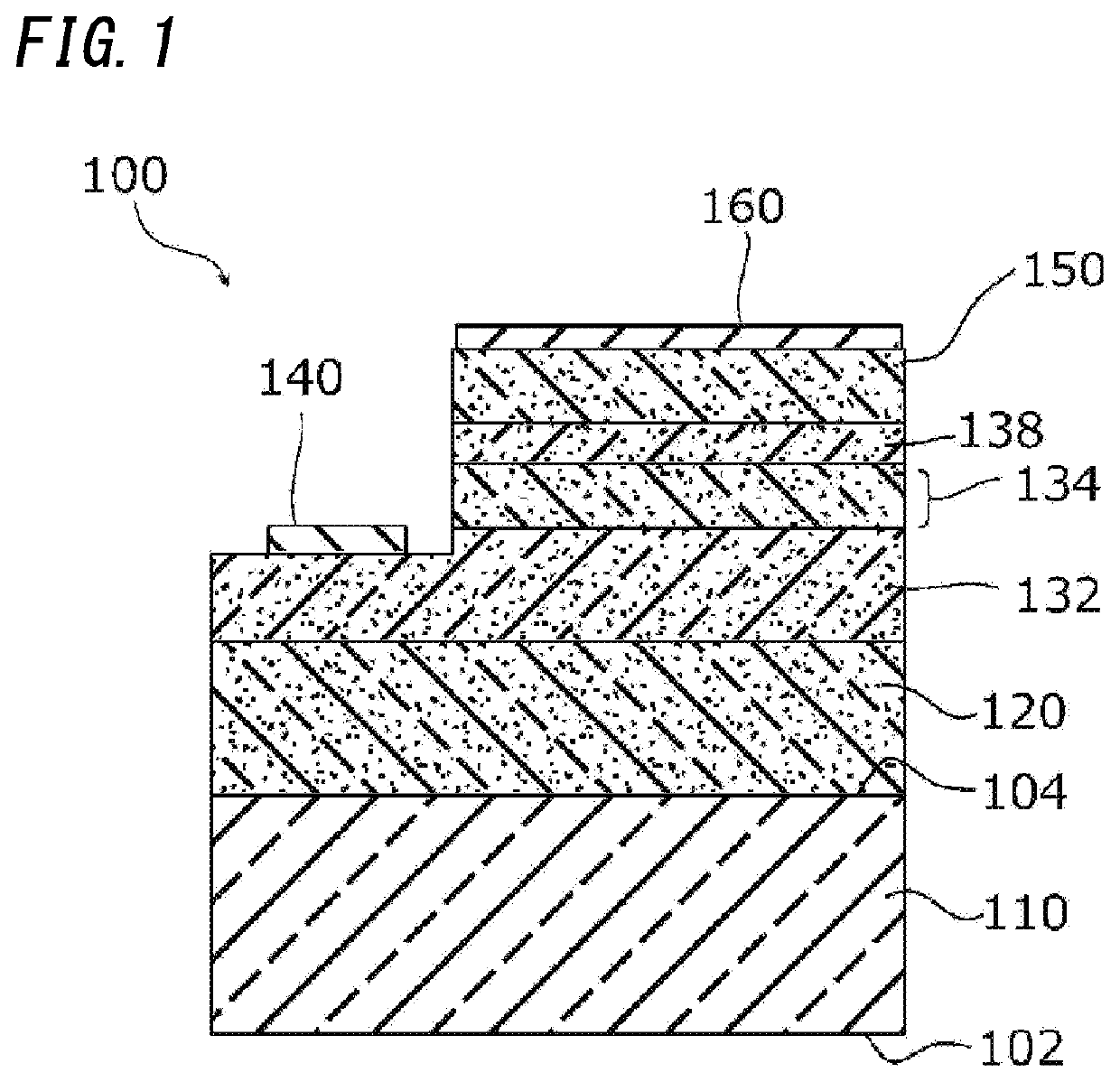
[0063]An ultraviolet light-emitting module including the UV LED element 100 was fabricated. An exemplary method for fabricating such an ultraviolet light-emitting module will be described.

[0064]First of all, a single-crystal sapphire substrate (α-Al2O3 substrate) is provided. In this case, the sapphire substrate has a first surface and a second surface, both of which intersect with the thickness direction of the sapphire substrate at right angles. The first surface of the sapphire substrate may have an off-axis angle of 0.20 degrees with respect to a (0001) plane, for example.

[0065]After the sapphire substrate has been provided, the sapphire substrate is loaded onto a susceptor in a reaction furnace of a metalorganic vapor phase epitaxy (MOVPE) system. Thereafter, with hydrogen (H2 gas) supplied as a carrier gas into the furnace of the MOVPE system, the furnace is warmed up until the in-furnace temperature reaches 1100° C. and the in-furnace pressure reaches 10 kPa...

second example

6-2. Second Example

[0074]After a UV LED element 100 has been fabricated in the same way as in the first example, six elements are electrically connected together in parallel and flip-chip bonded on a sub-mount. Subsequently, an amorphous fluorine resin is applied to cover those six elements entirely and then allowed to cure in the same curing condition as in the first example, thus fabricating an ultraviolet light-emitting module to operate with high output power. When this ultraviolet light-emitting module was supplied with a DC current of 120 mA, emission characteristics including a wavelength of 277 nm and an optical output power of 40 mW were achieved.


PUM

PropertyMeasurementUnit
valence band energyaaaaaaaaaa
wavelength rangeaaaaaaaaaa

Abstract

A UV LED element, which is an exemplary ultraviolet light-emitting diode according to the present invention, includes an n-type conductive layer, a light-emitting layer, an electron block layer, and a p-type contact layer, all of which are arranged in this order. Bandgap energy of the electron block layer satisfies Econtact≤EEBL, where Econtact designates bandgap energy of the p-type contact layer and EEBL designates the bandgap energy of the electron block layer. The electric apparatus includes the UV LED element as a light source for emitting an ultraviolet ray.

Description

TECHNICAL FIELD[0001]The present invention relates to an ultraviolet light-emitting diode and an electric apparatus including the light-emitting diode, and more particularly relates to an ultraviolet light-emitting diode with improved carrier injection efficiency and an electric apparatus including such a light-emitting diode.BACKGROUND ART[0002]Blue light-emitting diodes have been extensively used in practice as solid-state light-emitting elements that use a nitride semiconductor. Meanwhile, ultraviolet light-emitting diodes (UV LEDs) using a nitride semiconductor have also been developed as solid-state light-emitting elements that emit a light ray falling within the ultraviolet range with a shorter wavelength (i.e., an ultraviolet ray). In the ultraviolet range, an ultraviolet ray falling within a deep ultraviolet range of 350 nm or less, inter alia, an ultraviolet ray falling within a wavelength range of about 260 nm to about 280 nm that forms part of a UV-C wavelength range, amo...

Claims


Application Information

Patent Timeline
Patent Type & Authority Patents(United States)
IPC IPC(8): H01L33/00H01L33/06H01L33/04
CPCH01L33/06H01L33/04H01L33/0075
Inventor HIRAYAMA, HIDEKIJO, MASAFUMIMINO, TAKUYANOGUCHI, NORIMICHITAKANO, TAKAYOSHISAKAI, JUN
Owner RIKEN
Learn More