
Miniaturized electronic systems with wireless power and near-field communication capabilities

a technology of electronic systems and wireless power, applied in the field of miniaturized electronic systems with wireless power and near-field communication capabilities, can solve the problems of affecting the physiological state and/or chemical condition of the tissue, affecting the physiological and chemical characterization of the tissue, and affecting the performance of the instrument, so as to minimize the adverse physical effects of the tissue, reduce interfacial stress, and minimize the effect of adverse physical effects

Active Publication Date: 2020-06-09
THE BOARD OF TRUSTEES OF THE UNIV OF ILLINOIS
View PDF4 Cites 2 Cited by
  • Summary
  • Abstract
  • Description
  • Claims
  • Application Information

AI Technical Summary

Benefits of technology

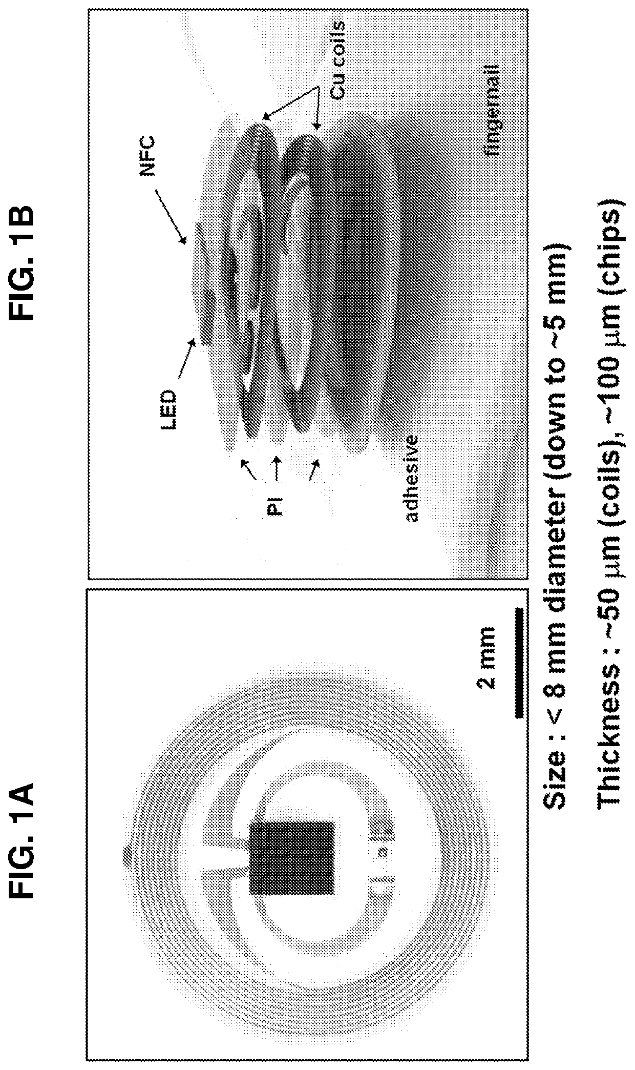
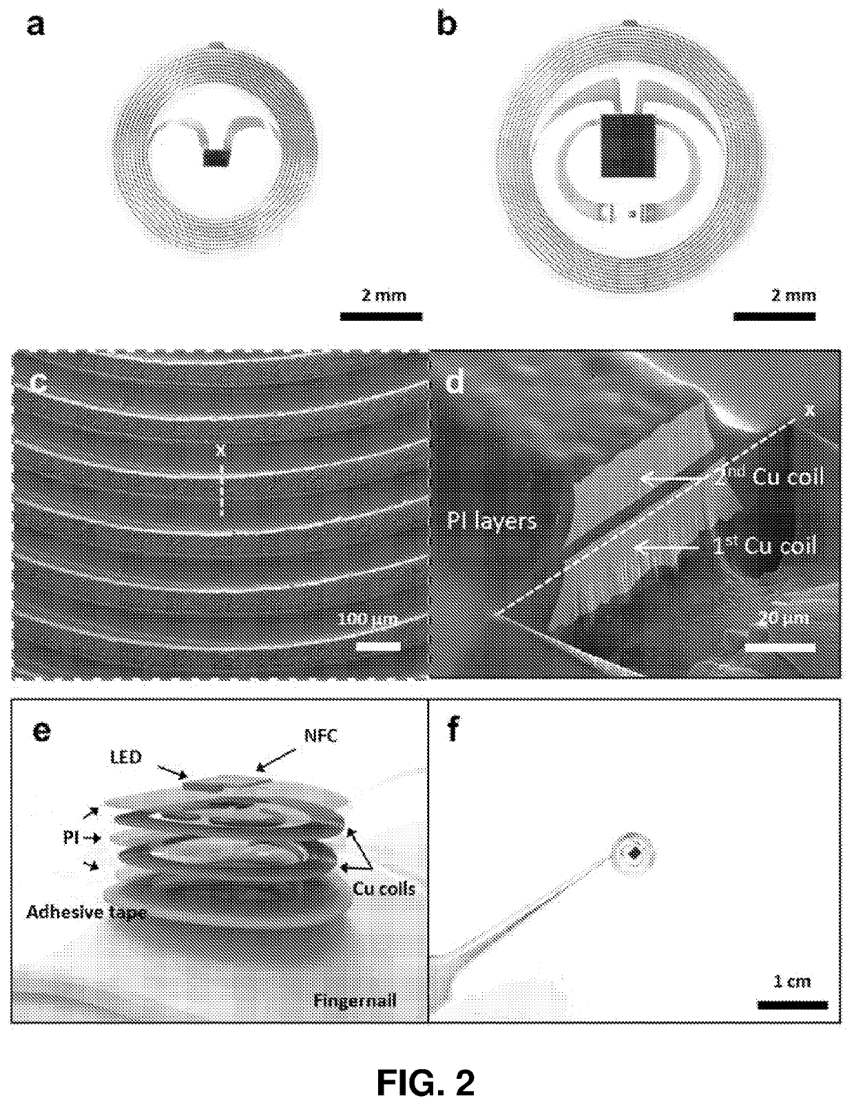
[0007]The invention provides systems and methods for tissue-mounted electronics and photonics. Devices of some embodiments of the invention implement high performance, and optionally flexible, device components having miniaturized formats in device architectures that minimize adverse physical effects to tissue and / or reduce interfacial stresses when mounted on tissue surfaces. In some embodiments, the invention provides complementary tissue mounting strategies providing for mechanically robust and / or long term integration of the present devices, for example, via mounting on tissue surfaces that are not subject to rapid growth or exfoliation processes such as the fingernail, toenail, tooth or earlobe. Devices of the invention are versatile and support a broad range of applications for sensing, actuating and communication including applications for near field communication, for example, for password authentication, electronic transactions and biometric sensing.
[0016]In some embodiments, the overall system geometry is designed to reduce or prevent delamination, for example, via having a tapered geometry. In an embodiment, for example, a portion of, or all, intersecting outer surfaces are joined radially at an angle to reduced or prevent delamination. In an embodiment, for example, the system is characterized by a gradual reduction of thickness in a range equal to or less than the center of the device to outer surface to reduce or prevent delamination. In an embodiment, for example, a thickness at an edge, such as an outer edge of the system or an edge of an aperture of the system, is at least 2 times, or at least 5 times, or at least 10 times, less than a thickness at a center (or mid-point between edges) of a system. In an embodiment, a thickness of the overall system decreases substantially asymptotically from a mid-point of the system to an edge, such as an outer edge of the system or an edge of an aperture of the system.
[0018]In some embodiments, the present systems incorporate an easy peel tab to facilitate deployment onto a tissue surface, for example, that can easily be discarded after mounting.
[0037]In some embodiments, for privacy, the invention has a devoted chip that stores an encrypted identification number that is unique to each individual device. In addition, the chip has action-specific security codes that change constantly. The encrypted device number helps keep patient health-care information private. Clinicians, hospital management, and insurance providers are the only users with access to the information. In case of emergency, hospital personnel can quickly locate missing patients and or observe patient vital signs.

Problems solved by technology

Despite considerable advances in tissue mounted systems a number of challenges remain in the development of certain applications for this technology.
First, conformal integration of these systems on some classes of tissue, such as the epidermis, can adversely impact the physiological state and / or chemical condition of the tissue, for example resulting in unwanted irritation and / or immune response.
Tissue mounted systems can also influence the exchange of heat, fluid and / or gas at the mounting site, thereby having the potential to interfere with physiological and chemical characterization of tissue.
Further, long term, reliable integration remains a challenge for some tissue types such as tissues characterized by rapid rates of growth, fluid exchange and / or exfoliation.

Method used


Image

  • Miniaturized electronic systems with wireless power and near-field communication capabilities
  • Miniaturized electronic systems with wireless power and near-field communication capabilities
  • Miniaturized electronic systems with wireless power and near-field communication capabilities

Examples


example 1

Abstract

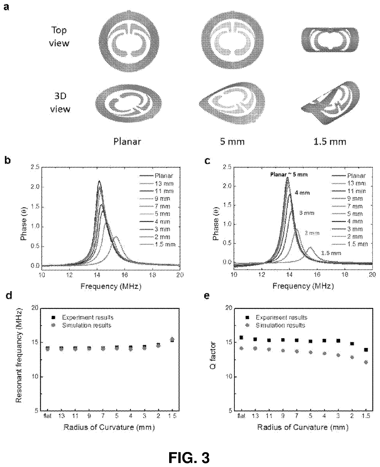
[0122]This Example introduces a class of thin, lightweight, flexible near field communication (NFC) devices with ultraminiaturized format, and presents systematic investigations of the mechanics, radio frequency characteristics and materials aspects associated with their optimized construction. These systems allow advantages in mechanical strength, placement versatility, and minimized interfacial stresses compared to other NFC technologies and wearable electronics. Detailed experimental studies and theoretical modeling of the mechanical and electromagnetic properties of these systems establish understanding of the key design considerations. These concepts can apply to many other types of wireless communication systems including bio-sensors and electronic implants.

Introduction

[0123]Wearable electronic technologies form the foundation for a rapidly growing consumer device segment. Projections suggest that over $100 billion will be spent in materials alone over the coming decad...

example 2

l Mounted NFC Device for Password Authentication

[0157]The invention provides, for example, a fingernail mounted near field communication (NFC) device providing a unique solution for password authentication in the electronic hardware industry. The materials, design, and circuit integration enable the art of biocompatible NFC technology. The built-in NFC technology serves as a digital replacement for passwords, pin numbers, security questions, distinct biometrics, and / or text / email verification dealings. The fingernail-mounted device of this embodiment is able to wirelessly communicate with point of access readers that use NFC antennas. The point of access readers include but are not limited to smartphones, laptops, keyboards, computer mice, remote controls, safes, and / or locks. Instead of recalling passwords, fingerprint touch pads, or safe combinations, authorized fingernail-mounted device users are granted instant access to their electronics and / or safe belongings without producing...

example 3

l Mounted NFC Device for Electronic Payments

[0176]The invention provides, for example, fingernail mounted near field communication (NFC) devices providing a unique platform for mobile payment and digital wallet service providers. The materials, design, and circuit integration enable the art of biocompatible NFC technology. In some embodiments, the built-in NFC technology serves as a digital replacement for the magnetic strip found on the back of all debit, credit, and prepaid gift cards. The fingernail-mounted device is able to wirelessly communicate with point of sale readers that use NFC antennas. Instead of exchanging cash, debit or credit cards, users have the ability to make secure in-store purchases with a single touch or point. Additional payment schemes using the fingernail-mounted device include device and pin, a combination of the devices, or a combination of the device and a second method for authorization.

[0177]In an embodiment, for example, the invention has a devoted c...


PUM


Abstract

The invention provides systems and methods for tissue-mounted electronics and photonics. Devices of some embodiments of the invention implement high performance, and optionally flexible, device components having miniaturized formats in device architectures that minimize adverse physical effects to tissue and / or reduce interfacial stresses when mounted on tissue surfaces. In some embodiments, the invention provides complementary tissue mounting strategies providing for mechanically robust and / or long term integration of the present devices, for example, via mounting on tissue surfaces that are not subject to rapid growth or exfoliation processes such as the fingernail, toenail, tooth or earlobe. Devices of the invention are versatile and support a broad range of applications for sensing, actuating and communication including applications for near field communication, for example, for password authentication, electronic transactions and biometric sensing.

Description

CROSS REFERENCE TO RELATED APPLICATIONS[0001]This application is a U.S. National Stage Application under 35 U.S.C. § 371 of International Application No. PCT / US2016 / 035336, filed Jun. 1, 2016, which claims the benefit of priority from U.S. Provisional Patent Application No. 62 / 169,308 filed Jun. 1, 2015, U.S. Provisional Patent Application No. 62 / 169,983 filed Jun. 2, 2015, U.S. Provisional Application No. 62 / 218,345 filed Sep. 14, 2015, and U.S. Provisional Application No. 62 / 218,321 filed Sep. 14, 2015, each of which is hereby incorporated by reference in its entirety to the extent not inconsistent herewith.STATEMENT REGARDING FEDERALLY SPONSORED RESEARCH OR DEVELOPMENT[0002]Not applicable.BACKGROUND OF INVENTION[0003]Wearable electronics and photonics are a class of systems with potential to broadly impact a range of technologies, industries and consumer products. Advances in wearable systems are driven, in part, by development of new materials and device architectures providing ...

Claims


Application Information

Patent Timeline
Patent Type & Authority Patents(United States)
IPC IPC(8): G06K19/06G06K19/07A61B5/00G01J1/42A61B6/00G01T1/00H02J50/30G01J5/10G06K19/077A61B5/1455
CPCG06K19/0723G01T1/00A61B6/00G06K19/0716G01J1/429G01J5/10G06K19/07722H02J50/30A61B5/6826G01J1/42A61B2562/0271A61B5/14552A61B2560/0214A61B2562/028A61B2560/0242H02J50/001H02J2310/23
Inventor ROGERS, JOHN A.BANKS, ANTHONY R.KIM, JEONGHYUNBROWN, GREGORY
Owner THE BOARD OF TRUSTEES OF THE UNIV OF ILLINOIS
Learn More