
Fracto-mechanoluminescent (FML) crystals-enhanced optical fiber-based impact sensor module

a technology of fracto-mechanoluminescent and optical fiber, applied in the direction of force measurement by measuring optical property variation, force/torque/work measurement apparatus, instruments, etc., can solve the problems of inability to detect damage occurrence below the surface of structural composites, limitations of the piezoelectric-based sensor network

Active Publication Date: 2020-07-21
NEW MEXICO TECH UNIV RES PARK COPORATION
View PDF13 Cites 3 Cited by
  • Summary
  • Abstract
  • Description
  • Claims
  • Application Information

AI Technical Summary

Benefits of technology

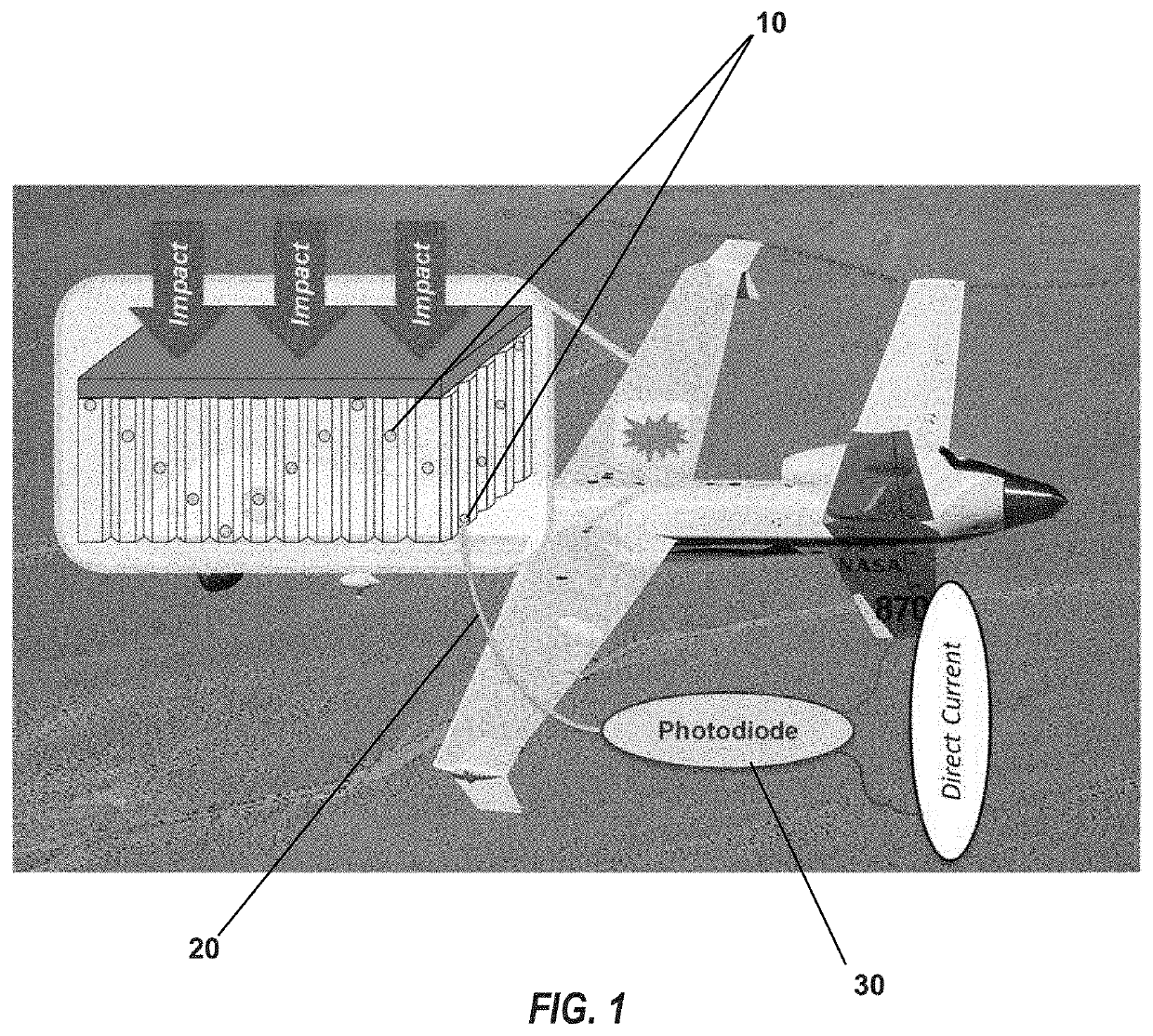
The present invention is a new sensor technology for detecting impacts on structural composites, particularly in aerospace structures. The invention uses fracto-mechanoluminescent (FML) materials and optical conductors to create a network of sensors that can detect strain or strain rate in a composite, without requiring constant power or heavy computational costs. The FML materials are embedded in an optically transparent material and the sensors can provide 3D impact sensing performance from anywhere within the composite, not just at the surface. The invention is an improvement over existing piezoelectric-based sensor networks as it can detect damage below the surface of the composite. The invention provides a more efficient and effective solution for detecting strain and damage in structural composites.

Problems solved by technology

Due to this intrinsic sensing mechanism, the piezoelectric-based sensor network has limitations as a sensor technology for structural health monitoring (SHM), which implements real-time damage detection technologies.
Furthermore, because the piezoelectric-based sensor network uses surface guided waves, damage occurrence below the surface of structural composites cannot be detected.

Method used


Image

  • Fracto-mechanoluminescent (FML) crystals-enhanced optical fiber-based impact sensor module
  • Fracto-mechanoluminescent (FML) crystals-enhanced optical fiber-based impact sensor module
  • Fracto-mechanoluminescent (FML) crystals-enhanced optical fiber-based impact sensor module

Examples


example 1

[0033]FIGS. 5A-5D show the representative sensor outputs at minimum and maximum impact energy from drop impact hammer tests with and without an aluminum top plate on a 76.2 mm×76.2 mm block of test composite comprising a 50.8 mm thick high-density polyethylene (HDPE) honeycomb core. An inner cell was lined with Mylar, and 62 mg of EuD4TEA crystals were added to the cell, which was then filled with a PDMS mixture. There are notable similarities between the sensor output with and without the aluminum top plate. The dips in the signal are caused by the impact hammer bouncing against the sample and causing more crystals to fracture. The mean output voltage was collected by averaging all of the data points above the threshold line. The threshold data was collected by a subroutine of the data acquisition system that runs before the test is ready. This subroutine takes 100 readings and returns either the average of the data or the highest noise value, whichever is larger. Any major discrep...

example 2

[0034]Synthesis of EuD4TEA FML crystals began from preparing a Europium(III) nitrate hydrate (ENH) / dibenzoylmethane (DBM) / trethylamine (TEA) solution in acetone. 8 mmol (=3424.34 mg) of ENH, 26 mmol (=5942.86 mg) of DBM, and 28 mmol (=3.9 mL) of TEA were added into 160 ml of acetone and manually stirred for 2 minutes without heating. Then, the solution was heated at about 40° C. and stirred at about 200 rpm for about 60 minutes on a hot plate. The solution was removed from the hot plate and covered with a paraffin film, which has a hole to allow slow evaporation of acetone at room temperature for about 48 hours. This slow acetone evaporation process is intended to allow EuD4TEA to form millimeter-size pellets as it crystallized. It should be noted that the evaporation time duration needs to be adjusted depending on the total volume of acetone. Precipitation of EuD4TEA crystals was observed about 4 hours after the room temperature evaporation is initiated. As time progresses, the siz...

example 3

[0044]EuD4TEA crystals were prepared according to the method of Example 2. To produce the composites for this example, aluminum and acrylic sheets were cut into 76.2 mm×76.2 mm squares. A sleeve of aluminum foil was placed on the wall of the center cell of a polypropylene honeycomb core. The reflective material was used to reflect all light emission from the EuD4TEA so it would be visible to the high-speed camera. PDMS was then poured into the center cell to the depth at which the EuD4TEA was to be situated and cured at 40° C. for 180 min. After the first layer was cured, EuD4TEA crystals were placed inside the cell, and more PDMS is added above the crystal and then cured. The test sample was then assembled in this order aluminum plate, polypropylene honeycomb, and acrylic sheet. The assembly is then fastened together using four nuts and four bolts. These are torqued to 5 Nm for consistent preloading. Once the assembly has been fastened together, the sides of the test sample were ma...


PUM


Abstract

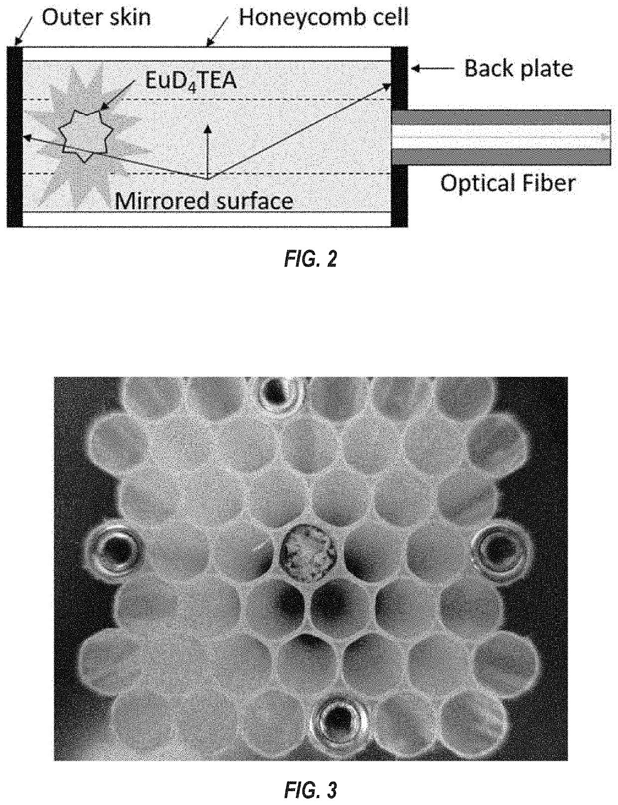
An Impact sensor for detecting strain or strain rate in a composite having one or more sensor nodes using a fracto-mechanoluminescent (FML) material, such as EuD4TEA crystals, encased in an optically transparent material such as PDMS. Optical fibers transmit light emitted by the FML material due to strain experienced by the composite. For honeycomb composites, the transparent material is disposed within cells of the honeycomb composite. A reflective material such as Mylar either surrounds the optically transparent material or lines the cell. The intensity of the light emitted by the FML material is related to the magnitude of strain or strain rate experienced by the composite as well as the distance of the FML material from the surface of the composite that receives the impact. Multiple sensor nodes disposed at different distances from the impact surface can provide a three-dimensional map of damage experienced by the composite.

Description

CROSS-REFERENCE TO RELATED APPLICATIONS[0001]This application claims priority to and the benefit of the filing of U.S. Provisional Patent Application No. 62 / 599,629, entitled “Fracto-Mechanoluminescent (FML) Crystals-Enhanced Optical Fiber-Based Impact Sensor Module”, filed on Dec. 15, 2017, the specification, appendices and attachments to, and claims of which are incorporated herein by reference.BACKGROUND OF THE INVENTIONField of the Invention (Technical Field)[0002]The present invention is related to impact sensors for structural composites.Background Art[0003]Note that the following discussion may refer to a number of publications and references. Discussion of such publications herein is given for more complete background of the scientific principles and is not to be construed as an admission that such publications are prior art for patentability determination purposes.[0004]One of the most advanced sensor technologies that is widely used for impact detection and localization fo...

Claims


Application Information

Patent Timeline
IPC IPC(8): G01L1/24G01B11/16C09K11/02
CPCC09K11/025G01B11/16G01L1/242G01B1/00G01L1/247G01L5/0052
Inventor RYU, DONGHYEONTOWLER, QUINLAN JAMES
Owner NEW MEXICO TECH UNIV RES PARK COPORATION
Learn More