Gradient coil with external direct cooling for brain magnetic resonance imaging

a brain magnetic resonance imaging and gradient coil technology, applied in the field of medical equipment, can solve the problems of limiting imaging resolution and sensitivity, limiting the performance of gradient coils, and conventional head-only gradient coils having two major technical limitations

Active Publication Date: 2020-08-11
UNITED STATES OF AMERICA +1
View PDF3 Cites 1 Cited by
  • Summary
  • Abstract
  • Description
  • Claims
  • Application Information

AI Technical Summary

Benefits of technology

[0048]It is therefore an object of the present invention to provide a gradient coil for patient brain imaging adapted specifically for brain Mill scanners through an ergonomic approach to overcome the problem of the limited shoulder clearance in conventional head-only gradient coils where a cylindrical coil carrier is modified with a slanted surface (at one end or both ends of the cylinder-shaped carrier) which are correlated to an anatomical disposition between the human shoulder and the neck.

Problems solved by technology

Gradient coils are particularly important in studies which explore brain structural connectivity, due to the fact that an insufficient magnetic field strength generated by a gradient coil may limit the imaging resolution and sensitivity that may be achievable in the MM scanners.
The performance of the gradient coil is one of the primary limiting factors in high speed, high resolution magnetic resonance imaging (MRI), and in diffusion MRI.
Unfortunately, conventional head-only gradient coils have two major technical limitations, including (a) a limited neck-shoulder clearance and (b) a limited cooling capacity.
Due to the fact that conventional MM scanners are designed to cover a large field of view, the gradient strength and the inductance of these coils are thus inherently limited by the physical size of the coil.
Furthermore, the peripheral nerve stimulation (PNS) and the cardiac stimulation (CS) are two physiological factors that ultimately limit the performance of a gradient coil.
Nevertheless, despite MRI technology advancement, there are still two major technical issues associated with the conventional gradient insert design which include: a) the “shoulder clearance” issue and (b) cooling.
However, since the inner diameter of the cylindrical coil does not provide clearance for the shoulders of a typical adult, one cannot place the center of the human brain at the center of the gradient coil where a uniform magnetic field is produced.
Due to this displacement, disadvantageously, only a fraction of the “sweet spot” (i.e., the uniform region) is used for neuroimaging.
However, the high current used in the operation of this gradient coil generates a large amount of heat.
However, the asymmetric head gradient also has several undesirable features, such as: in the asymmetric design, it is more difficult to balance the torque and to provide effective eddy current shielding, and, the linearity of the gradient field is much poorer than in conventional symmetric design.
An additional shortcoming of the asymmetric design is, that due to the fact that Maxwell terms (concomitant terms) include odd orders, as well as even orders, their effect on the diffusion pulse sequence is undesirably complicated.
While some of these problems (such as the image distortions associated with gradient field nonlinearity might be manageable by applying reconstruction processing principles, in a diffusion MRI, b-factors associated with diffusion concomitant terms and their effect on fiber tracking might be less straightforward to quantify.
In a gradient coil, half of the loop generates a desired magnetic field, while the other half (the return path) is necessary to complete the electrical loop, however, the return path generates an undesired field, and takes up space, thus increasing the length of the coil in a traditional design.
It is quite a technical challenge to optimize the magnetic field in the target volume due to the physical constraints.
Notably, a conceptually similar, but more extreme approach had been developed in which the return paths were co-axial to the active segments along the radial direction, and thus did not contribute to the overall length of the coil.
However, the efficiency in this system is relatively lower than that in the conventional transverse gradient coil.
However, this arrangement only applies to an “open magnet”, which is used in the “open MRI” systems with clinical applications in low magnetic field strength (typically <0.5 Tesla), but has never been applied in the high field MRI (1.5 Tesla and above), because it is extremely challenging to generate uniform high magnetic field with the open magnet.
However, this system, using cooling pipes, is susceptible to shortcomings associated with indirect cooling and direct internal cooling, and this design is only suitable for whole body MM system.
The natural convection suffers from extremely low heat transfer coefficient, leading to limited thermal management capacity.
In such a case, it is extremely challenging to maintain low surface temperature using high flow rate while keeping the pressure drop in a reasonable range (less than 200 pounds per square inch (PSI)), because practically most materials (e.g. hoses and tubes) cannot withstand a high pressure.
None of the conventional Mill scanners has solved the “shoulder clearance” problem in a single magnet bore arrangement.
In addition, none of the prior art gradient coils used in the Mill scanners has overcome the shortcomings of the traditional cooling systems based on coolant flowing in tubes for cooling the gradient coils.

Method used


Image

  • Gradient coil with external direct cooling for brain magnetic resonance imaging
  • Gradient coil with external direct cooling for brain magnetic resonance imaging
  • Gradient coil with external direct cooling for brain magnetic resonance imaging

Examples


Embodiment Construction

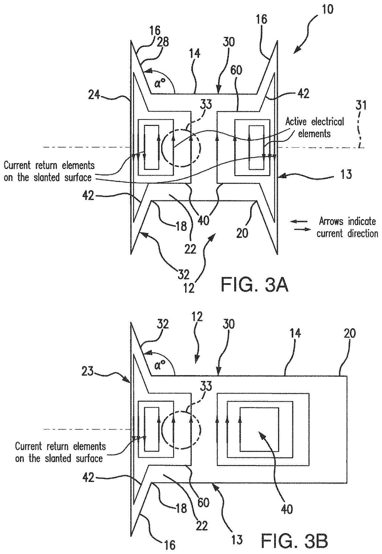
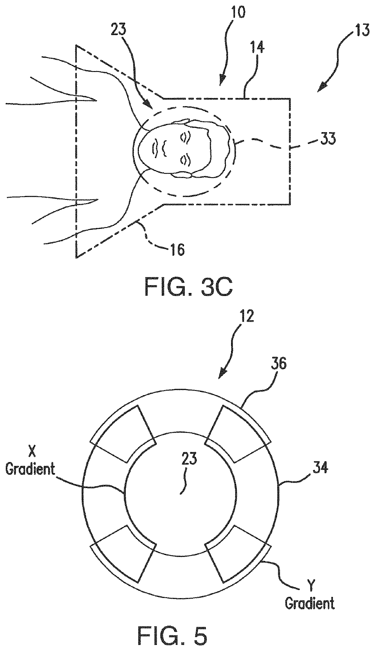
[0084]Referring to FIGS. 3A-3C, 4A-4C, 5, 6A-6C, and 7-11B, the subject system 10 and method provide a unique solution for two major limiting factors of the conventional coil gradient technologies for head MRI scanning, namely, the “shoulder clearance” problem and heat dissipation. The design of the present gradient coil 12 is supported by an ergonomic approach, i.e., widening the entrance into the bore of the gradient coil to allow the shoulder clearance, enhanced by placing the current return paths on slanted planes which extend in parallel to the outline of the shoulders of the human patient. This effectively eliminates the limiting factor from the return paths that contribute to the length of the coil, while maintaining torque balance, and moving the region of the homogeneous field closer to the entrance of the system.

[0085]As shown in FIGS. 3A-3B and 4A-4C, the subject system 10 includes a gradient coil 12 secured in a predetermined fashion on a gradient coil holder housing 13 ...


PUM


Abstract

The gradient coil assembly is designed to address a neck-shoulder clearance problem by configuring the coil holder housing with a cylindrical portion modified with a slanted surface and positioning current return elements of the coil pattern at the slanted surface, while positioning the active electrical elements on the cylindrical surface, thus eliminating influence of an undesired magnetic field generated by the current return elements, shortening the coil, and moving the homogeneous field gradient region toward the end of the cylindrical portion of the bore in the coil holder housing. The subject assembly operation is further improved by the direct external cooling approach, where a coolant flows in direct contact with electrical wires of the gradient coil inside the cooling channels in the surface of the coil holder housing.

Description

REFERENCE TO RELATED APPLICATIONS[0001]This Utility Patent Application is based on the Provisional Patent Application Ser. No. 62 / 613,597, filed on 4 Jan. 2018.FIELD OF THE INVENTION[0002]The present invention is directed to medical equipment, and specifically, to a gradient coil design for Magnetic Resonance Imaging (MM) scanners.[0003]More in particular, the present invention is directed to a gradient coil for MRI scanners having an improved wiring pattern, adapted for a patient's head MRI scanning, and equipped with an enhanced cooling design to permit operation with a high current density in the gradient coil, thus substantially increasing the magnetic field strength and homogeneity.[0004]The present invention is also directed to a short gradient coil for MRI scanners specifically configured for brain imaging which is capable of attaining positioning of the head within the magnet bore of the MM scanner in alignment with the homogeneous magnetic field region generated by the grad...

Claims


Application Information

Patent Timeline
Patent Type & Authority Patents(United States)
IPC IPC(8): G01R33/385
CPCG01R33/3856G01R33/3858G01R33/385
Inventor YANG, BAOLU, HANBINGYANG, ZHI
Owner UNITED STATES OF AMERICA
Why Eureka
Try Eureka