
Electrode structure including electrode fiber having higher density of vertical tows to parallel tows, flow battery stack including the same, and sealing structure including sealing gaskets connected by sealing wire

a flow battery and electrode fiber technology, applied in the field of flow battery technology, can solve the problems of large difference in flow rate and resistance of electrolyte at the center and both sides of the surface of the electrode, direct affecting the reliability, safety and cost of the entire flow battery system, and reducing contact resistance. , good mechanical properties, the effect of reducing the contact resistan

Active Publication Date: 2021-07-13
DALIAN RONGKE POWER
View PDF4 Cites 0 Cited by
  • Summary
  • Abstract
  • Description
  • Claims
  • Application Information

AI Technical Summary

Benefits of technology

The present invention provides an electrode structure for a flow battery that reduces contact resistance, improves mechanical properties, and increases energy output per unit power. The electrode has a three-layer structure with a center layer made of rayon and two layers made of polyacrylonitrile-based material. This structure ensures good contact with the ion membrane and the bipolar plate and reduces mass transfer unevenness when the electrolyte flows through the inside of the electrode. The electrode has a uniform structure after compression, with layers of different thickness depending on porosity. The preparation process is simple and easy to implement, and the power performance of the flow battery is optimized to the greatest extent with minimal production cost.

Problems solved by technology

Stack is a main core component of the flow battery system, and its power performance directly affects the reliability, safety and cost of the entire flow battery system.
High contact resistance may significantly limit properties of the flow battery such as discharge power and voltage efficiency.
After being assembled into a stack, a porosity of the carbon felt or the graphite felt varies in a thickness direction due to a pressing force applied on two sides, the porosity on both sides is much smaller than the porosity at the center, the unevenness of the porosity will result in a large difference in the flow rate and the resistance of the electrolyte at the center and at both sides of the surface of the electrode.
This will lead to problems such as uneven electrolyte distribution, uneven electrochemical reaction, uneven current transfer and heat transfer in the flow battery stack, and reduce the energy efficiency and life of the stack.

Method used


Image

  • Electrode structure including electrode fiber having higher density of vertical tows to parallel tows, flow battery stack including the same, and sealing structure including sealing gaskets connected by sealing wire
  • Electrode structure including electrode fiber having higher density of vertical tows to parallel tows, flow battery stack including the same, and sealing structure including sealing gaskets connected by sealing wire
  • Electrode structure including electrode fiber having higher density of vertical tows to parallel tows, flow battery stack including the same, and sealing structure including sealing gaskets connected by sealing wire

Examples


example 1

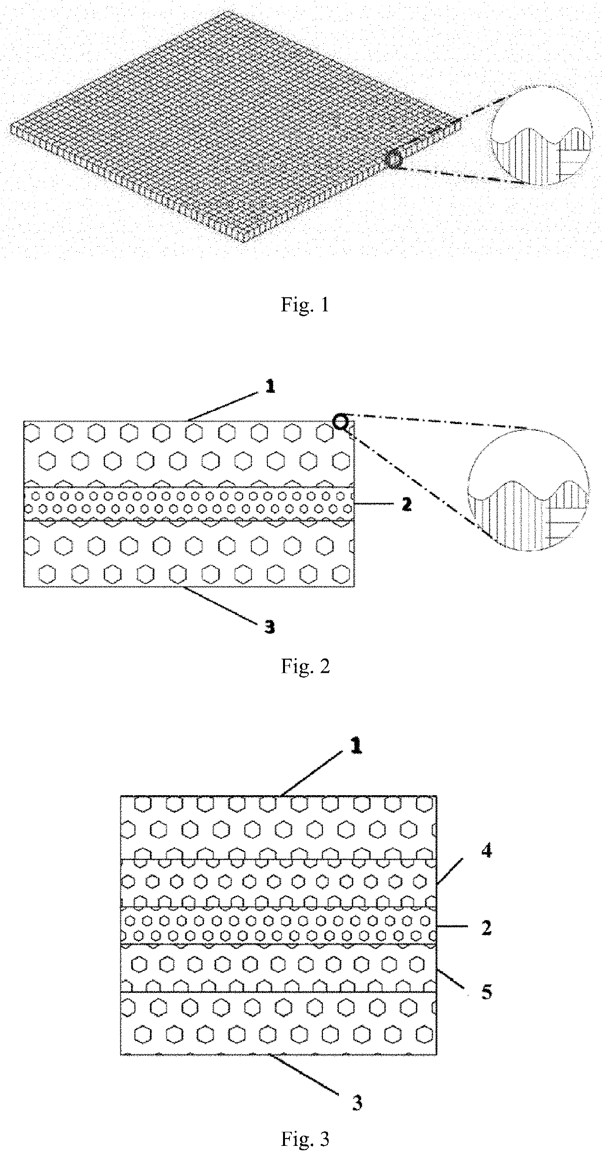
[0038]As shown in FIG. 2, an electrode structure comprises three layers of electrode fibers, which are an electrode fiber layer 1 near a bipolar plate, an electrode fiber layer 2 located at a center and an electrode fiber layer 3 near an ion membrane side, wherein the three layers of raw materials are all polyacrylonitrile-based material, a density ratio of the vertical tow and the parallel tow is 6:4, and a diameter of the vertical tow is 6 μm; the structure of the electrode fiber layer 1 and the electrode fiber layer 3 is as follows: porosity of 95% and thickness of 3 mm; and the electrode fiber layer 2 has a porosity of 92.5% and a thickness of 1.5 mm, and the surface contacting with the graphite bipolar plate or the ion membrane is provided with a convex spinous structure and has a high and low undulation shape. When the electrode is in close contact with the bipolar plate with an overall porosity reaches 91%, the vertical resistivity thereof is recorded, then the electrode is a...

example 2

[0041]As shown in FIG. 3, an electrode structure comprises five layers of electrode fibers, which are an electrode fiber layer 1 near a bipolar plate, an electrode fiber layer 2 located at a center and an electrode fiber layer 3 near an ion membrane side, an electrode fiber layer 4 disposed between the electrode fiber layer 1 and the center electrode fiber layer 2, and an electrode fiber layer 5 disposed between the electrode fiber layer 2 and the electrode fiber layer 3, wherein the five layers of raw materials are all polyacrylonitrile-based material, a density ratio of the vertical tow to the parallel tow is 7:3, and a diameter of the vertical tow is 18 μm. The structure of the electrode fiber layer 1 and the electrode fiber layer 3 is as follows: a porosity of 94% and a thickness of 2 mm; the structure of the electrode fiber layer 4 and the electrode fiber layer 5 is as follows: a porosity of 93% and a thickness of 1 mm and the electrode fiber layer 2 has a porosity of 92% and a...

example 3

[0043]As shown in FIG. 3, an electrode structure comprises five layers of electrode fibers, which are an electrode fiber layer 1 near a bipolar plate side, an electrode fiber layer 2 located at a center and an electrode fiber layer 3 near an ion membrane side, an electrode fiber layer 4 disposed between the electrode fiber layer 1 and the electrode fiber layer 2, and an electrode fiber layer 5 disposed between the electrode fiber layer 2 and the electrode fiber layer 3. Wherein the raw materials of the electrode fiber layer 1, electrode fiber layer 3, electrode fiber layer 4 and electrode fiber layer 5 are polyacrylonitrile-based material, while the raw material of the electrode fiber layer 2 is rayon-based material, a density ratio of the vertical tow to the parallel tow is 6.5:3.5, and a diameter of the vertical tow is 7 μm. The structure of the electrode fiber layer 1 and the electrode fiber layer 3 is as follows: a porosity of 95%, a thickness of 2 mm, and the surface contacting...


PUM

PropertyMeasurementUnit
porosityaaaaaaaaaa
porosityaaaaaaaaaa
thicknessaaaaaaaaaa

Abstract

An electrode structure of a flow battery, a flow battery stack, and a sealing structure of the flow battery stack, wherein the density of the vertical tow in the electrode fiber is larger than the density of the parallel tow. In the electrode fiber per unit volume, the quantity ratio of the vertical tow to the parallel tow is at least 6:4. The electrode structure is composed of an odd number of layers of the electrode fibers, and the porosity of other layers is larger than the porosity of the center layer. The electrode structure is mainly composed of the vertical tows perpendicular to the surface of the electrode, so that, firstly, the contact area between the outer surface of the electrode and the adjacent component can be increased and the contact resistance can be reduced, secondly, the electrode is endowed with good mechanical properties, compared with the original structure, the contact resistance of such structure is reduced by 30%-50%; and the layers of the electrode have different thickness depending on the porosity, after compression, the layers with optimized thickness have a consistent porosity, this compressed uniform structure avoids uneven mass transfer phenomena when the electrolyte flows through the electrode, and reduces the concentration polarization of the battery and thereby improving the battery energy output under the given power.

Description

RELATED APPLICATIONS[0001]The present application is a National Phase of International Application Number PCT / CN2017 / 109236, filed Nov. 3, 2017, and claims the priority of China Application No. 201610986518.6, filed Nov. 9, 2016; and China Application No. 201611132210.1, filed Dec. 9, 2016.FIELD OF THE INVENTION[0002]The present invention relates to the field of flow battery technology, and more particularly to an electrode structure of a flow battery and a flow battery stack.BACKGROUND OF THE INVENTION[0003]As a large-scale energy storage technology, the flow battery system has received extensive attention due to its advantages of reliability, safety, flexible location, independent design of capacity and power, etc. Stack is a main core component of the flow battery system, and its power performance directly affects the reliability, safety and cost of the entire flow battery system. The main factors affecting the power performance of the flow battery stack include ohmic polarizatio...

Claims


Application Information

Patent Timeline
Patent Type & Authority Patents(United States)
IPC IPC(8): H01M4/75H01M8/0273H01M8/18H01M4/02
CPCH01M4/75H01M8/0273H01M8/188H01M2004/021Y02E60/10H01M4/861H01M4/8657H01M4/8636H01M8/0276H01M8/2455H01M8/2483Y02E60/50H01M8/20
Inventor LIU, SHENGLINJIANG, HONGDONGZHANG, HUAMINMA, XIANGKUNZHANG, TAOJIANG, SHANYANG, ZHENKUNSUN, DANYI, KUANRONG
Owner DALIAN RONGKE POWER
Learn More