Focusing light inside scattering media with magnetic particle guided wavefront shaping

a scattering medium and magnetic particle technology, applied in the field of imaging and focusing electromagnetic radiation in a scattering medium, can solve the problems of low coherence of fluorescence, inaccessible target planes inside the scattering medium, and conventional optics of focusing ligh

Active Publication Date: 2021-10-26
CALIFORNIA INST OF TECH +1
View PDF6 Cites 0 Cited by
  • Summary
  • Abstract
  • Description
  • Claims
  • Application Information

AI Technical Summary

Problems solved by technology

However, the strong optical scattering inherent to many types of biological tissue prevents conventional optics from focusing light beyond depths of ˜1 mm, since at this depth nearly all the light has been scattered [1].
In practice, however, the target plane inside the scattering medium is often not directly accessible, especially when minimally invasive approaches are desired.
However, fluorescence has low coherence and second harmonic generation is generally inefficient, limiting their working depth with DOPC.
Because optical absorption alone cannot generate light for phase conjugation and coherence gating is limited to shallow depths, these approaches are not suitable for DOPC either and have not been used as guidestars for DOPC thus far.
While ultrasound offers excellent localization, it also introduces intrinsic drawbacks such as large focal volume, low modulation efficiency, lack of biomolecule specificity, strong attenuation at high frequency, low penetration through some structures like bones or gas, and the need for coupling agents.
Although ultrasound microbubbles address the first three problems of the ultrasound guidestar, the microbubbles are largely limited to applications in the vasculature.
Instead, it utilizes the intrinsic motion of an object such as a flowing red blood cell [31,32], which largely limits its biomedical applications to the vasculature.
Moreover, one cannot freely control the location of the focus.

Method used


Image

  • Focusing light inside scattering media with magnetic particle guided wavefront shaping
  • Focusing light inside scattering media with magnetic particle guided wavefront shaping
  • Focusing light inside scattering media with magnetic particle guided wavefront shaping

Examples


embodiment 15

[0129]16. The apparatus 100 of embodiment 15, wherein the in vivo decorrelation time is reduced to at least 50 milliseconds using an immobilization approach.

[0130]17. The apparatus 100 of one or any combination of the previous embodiments, wherein the detector 110, 116 has a frame rate of greater than 20 Hz, the spatial light modulator SLM has response rate of greater than 20 Hz, and the input electromagnetic radiation 126 has an intensity up to 200 mW / cm2 (e.g., for tissue safety).

[0131]18. The apparatus 100 of one or any combination of the previous embodiments, wherein the phase conjugate mirror comprises a nonlinear optical device (e.g., photorefractive crystal, polymer film).

example

[0132 Method of Operation

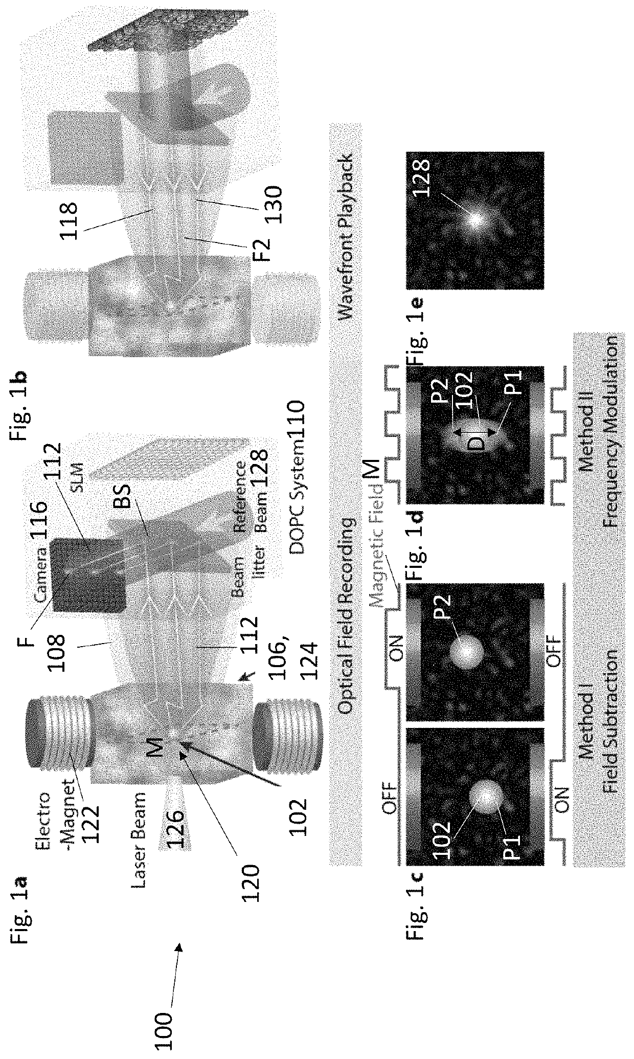
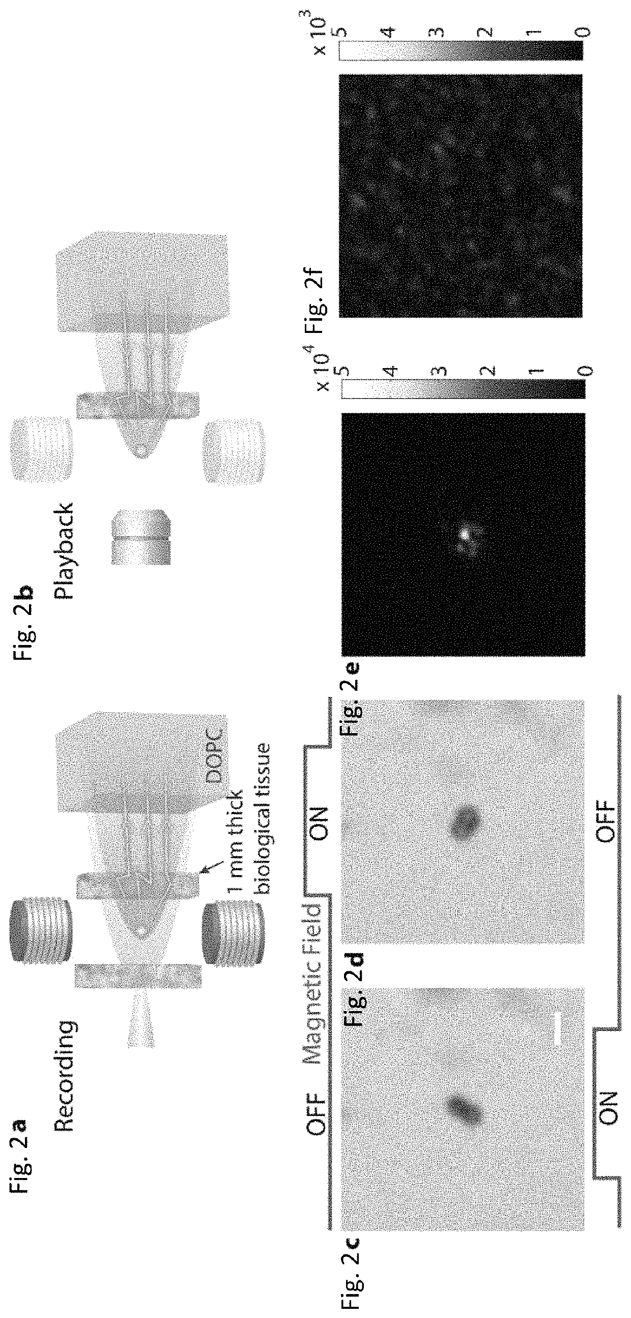
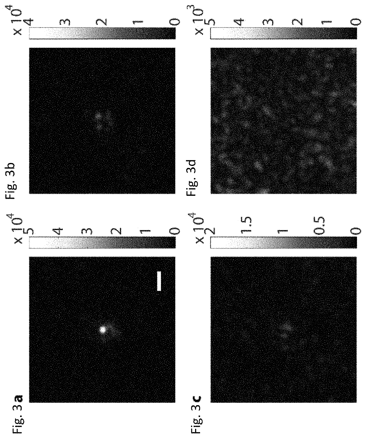
[0133]FIG. 12 illustrates a method for irradiating a scattering medium 124.

[0134]Block 1200 represents applying a magnetic field to a magnetic particle 102 in a scattering medium 124 so that the magnetic field moves the magnetic particle 102 in the scattering medium 124. Examples of scattering media include, but are not limited to, biological tissue.

[0135]Block 1202 represents irradiating the magnetic particle 102 in the scattering medium 124 with electromagnetic radiation 126, wherein the electromagnetic radiation scatters from the magnetic particle 102 so as to form scattered electromagnetic radiation 112.

[0136]Block 1204 represents forming a recording of the scattered electromagnetic radiation 112112 on a detector 110, 116 or a phase conjugate mirror. In one or more examples, the recording comprises an interference pattern recording interference between a reference beam 140 and the scattered electromagnetic radiation 112 on a camera or a phase conjugate m...


PUM

PropertyMeasurementUnit
diameteraaaaaaaaaa
depthsaaaaaaaaaa
diameteraaaaaaaaaa

Abstract

A magnetic field controlled guidestar for focusing light deep inside scattering media using optical phase conjugation. Compared with the optical and ultrasonic field, the magnetic field has an exceptional penetration depth. The magnetic particle guidestar has a high light-tagging efficiency, good biocompatibility, and a small diameter which enables a sharp and bright focusing deep inside biological tissue. This new method can benefit a wide range of biomedical applications including deep-tissue imaging, neural modulation, and targeted photothermal and photodynamic therapies.

Description

CROSS REFERENCE TO RELATED APPLICATIONS[0001]This application claims the benefit under 35 U.S.C. Section 119(e) of the following and commonly-assigned applications:[0002]U.S. Provisional Patent Application Ser. No. 62 / 542,656, filed on Aug. 8, 2017, entitled “FOCUSING LIGHT INSIDE SCATTERING MEDIA WITH MAGNETIC PARTICLE GUIDED WAVEFRONT SHAPING,” by Haowen Ruan and Changhuei Yang, and[0003]U.S. Provisional Patent Application Ser. No. 62 / 564,850, filed on Sep. 28, 2017, entitled “FOCUSING LIGHT INSIDE SCATTERING MEDIA WITH MAGNETIC PARTICLE GUIDED WAVEFRONT SHAPING,” by Haowen Ruan, Changhuei Yang, Jacob Berlin, and Tom Haber;[0004]which applications are incorporated by reference herein.STATEMENT REGARDING FEDERALLY SPONSORED RESEARCH AND DEVELOPMENT[0005]This invention was made with government support under Grant No. NS090577 awarded by the National Institutes of Health. The government has certain rights in the invention.BACKGROUND OF THE INVENTION1. Field of the Invention[0006]This...

Claims


Application Information

Patent Timeline
Patent Type & Authority Patents(United States)
IPC IPC(8): G01N21/47G03H1/04G01N33/483G03H1/22G03H1/00
CPCG03H1/0443G01N21/4795G01N33/4833G03H1/0005G03H1/0465G03H1/2294G03H2001/0083G03H2001/0447G03H2001/0458G03H2001/0471G03H2225/30
Inventor RUAN, HAOWENBERLIN, JACOBHABER, TOMYANG, CHANGHUEI
Owner CALIFORNIA INST OF TECH
Why Eureka
Try Eureka