
Method for forming insulating film, apparatus for processing substrate, and system for processing substrate

a technology of insulating film and substrate, applied in the direction of liquid surface applicators, liquid/solution decomposition chemical coatings, coatings, etc., can solve the problems of difficult hydrolysis promotion, low throughput, and method is difficult to be used in a production line, so as to reduce the amount of remaining without hydrolysis, increase the production efficiency of hydroxyl groups, and reduce the effect of energy for hydrolysis

Active Publication Date: 2022-04-26
TOKYO ELECTRON LTD
View PDF10 Cites 3 Cited by
  • Summary
  • Abstract
  • Description
  • Claims
  • Application Information

AI Technical Summary

Benefits of technology

The present invention provides a technology for making high-quality insulating films containing silicon oxide on a substrate. The technology involves applying a coating liquid containing a precursor of the insulating film to the substrate, evaporating the solvent in the coating liquid, and curing the coated film in a low-oxygen atmosphere. This process increases the production efficiency of hydroxyl groups and facilitates dehydration condensation, resulting in a dense and good-quality insulating film. The quality of the coated film can also be improved by forming a protective film on its surface after curing.

Problems solved by technology

The reason that oligomer is used as a component of the coating liquid is because when all of precursor is connected, it is not solved in a solution.
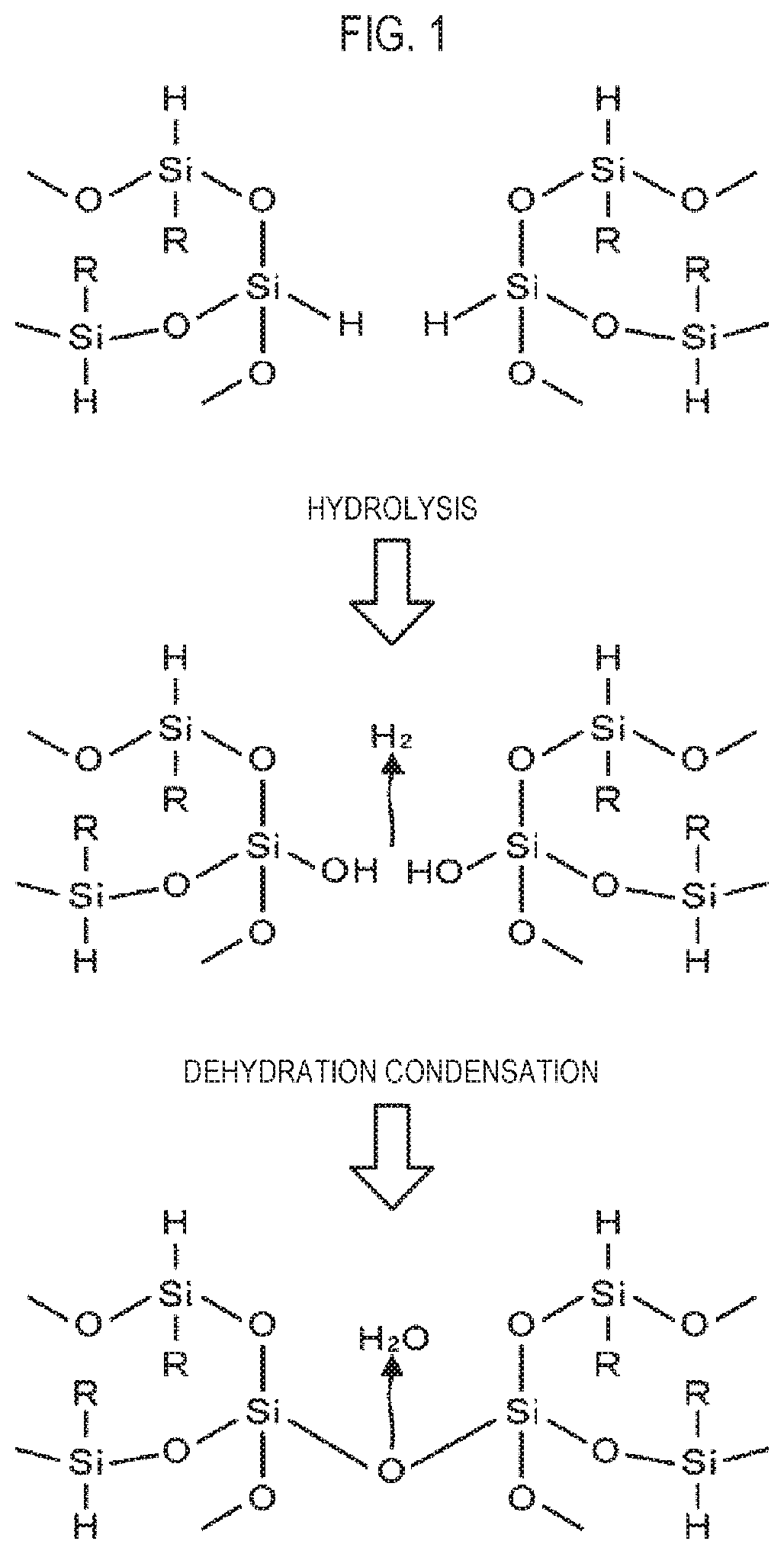
For these reasons, the state of oligomer, that is, the state of the precursor before the hydrolysis described above is stable and the hydrolysis is a process that changes the stable state into an unstable state, so it is difficult to promote hydrolysis.
Further, according to the method of performing curing for long time at a low temperature, the throughput is low, so the method is difficult to be used in a production line.

Method used


Image

  • Method for forming insulating film, apparatus for processing substrate, and system for processing substrate
  • Method for forming insulating film, apparatus for processing substrate, and system for processing substrate
  • Method for forming insulating film, apparatus for processing substrate, and system for processing substrate

Examples


first embodiment

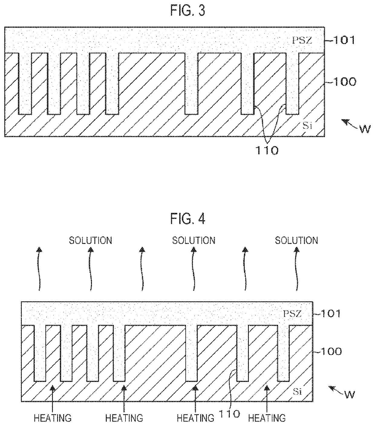
[0050]Next, an embodiment of a method of forming an insulating film of the present disclosure is described in detail. As a method of forming an insulating film using the system for processing a substrate, a process of performing STI on a target substrate is described. As shown in FIG. 3, grooves 110 (trenches) are formed in a silicon film 100 of a wafer W that is a target substrate. A coating liquid obtained, for example, by dissolving a precursor of SOG film in an organic solution is applied to the wafer W, whereby a coated film 101 is formed to fill the trenches 110. For example, polysilazane that is a polymer having —(SiH2)NH— as a fundamental structure is used as the precursor. In the coating liquid, for example, molecular groups of polysilazane are dissolved in an oligomer state to improve fluidity. Accordingly, as shown in FIG. 3, when a coating liquid is applied to the wafer W, for example, by spin coating, the coating liquid easily enters the narrow trenches 110, so that the...

second embodiment

[0095]Next, a method of forming an insulating film according to a second embodiment of the present disclosure is described. In this embodiment, after the process of radiating the ultraviolet rays to the coated film 101 shown in FIG. 5, the ultraviolet rays are further radiated to the coated film. For example, the ultraviolet rays of a dosage of 2000 mJ / cm2 are radiated when the ultraviolet rays are primarily radiated to the coated film, and then the ultraviolet rays of a dosage of 1000 mJ / cm2 are radiated as a process of secondarily radiating the ultraviolet rays to the coated film.

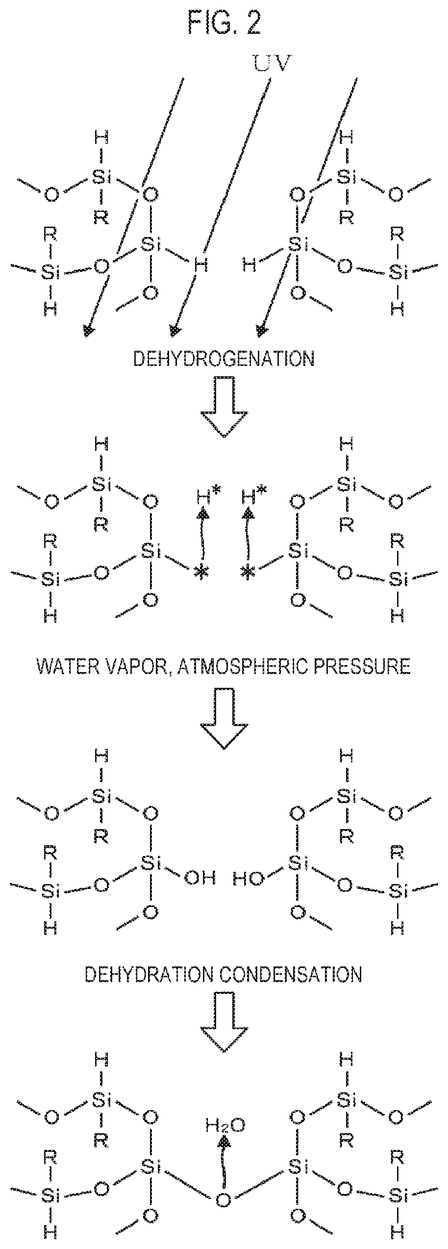
[0096]The amount of energy that is supplied to the coated film and activity of the coated film are described. As shown in the schematic diagram of FIG. 18, when energy is radiated to a coated film, energy exceeding a predetermined tolerance E1 is given to form dangling bonds. However, when energy exceeding a tolerance E2 is further given, activity of the coated film excessively increases, whereby the acti...

example 1

[0121]An example defined as Example 1 was conducted by radiating ultraviolet rays having a main wavelength of 172 nm in a N2 gas atmosphere in the process of radiating the ultraviolet rays in the method of forming an insulating film such that the dosage becomes 2000 mJ / cm2. In Example 1, the coating liquid described in the embodiment was applied to the wafer W, the wafer W is heated at 150 degrees C. for 3 minutes in the solution volatilization process, and then the process of radiating the ultraviolet rays was performed without performing the reflow process. Next, the wafer W was transferred to a heat treatment apparatus without being left for a period. Subsequently, in the curing process, the wafer W was heated through two stages performed at 400 degrees C. for 30 minutes and at 450 degrees C. for 120 minutes with water vapor supplied in a heat treatment furnace, and then the wafer W was heated at 450 degrees C. in a N2 gas atmosphere. The target thickness of a coated film was 100...


PUM

PropertyMeasurementUnit
wavelengthaaaaaaaaaa

Abstract

There is provided a technique of forming an insulating film containing silicon oxide. A coating solution containing polysilazane is applied onto a wafer W, the solvent of the coating solution is volatilized, and the coating film is irradiated with ultraviolet rays in nitrogen atmosphere before performing a curing process. Dangling bonds are generated in silicon which is a pre-hydrolyzed site in polysilazane. Therefore, the energy for hydrolysis is reduced, and unhydrolyzed sites are reduced even when the temperature of the curing process is 350° C. Since efficient dehydration condensation occurs, the crosslinking rate is improved, and a dense (good-quality) insulation film is formed. By forming a protective film on the surface of the coating film to which ultraviolet rays irradiated, the reaction of dangling bonds prior to the curing process is suppressed.

Description

[0001]This is a National Phase Application filed under 35 U.S.C. 371 as a national stage of PCT / JP2018 / 031810, filed Aug. 28, 2018, an application claiming the benefit of Japanese Application No. 2017-174287, filed Sep. 11, 2017, the content of each of which is hereby incorporated by reference in its entirety.TECHNICAL FIELD[0002]The present disclosure relates to a technology of forming an insulating film that is a silicon oxide-containing coated film and is hardened by a cross-linking reaction.BACKGROUND[0003]There is a process of forming an insulating film such as a silicon oxide film in the processes of manufacturing semiconductor devices. The insulating film is formed, for example, by plasma CVD or by applying a coating liquid. An insulating film formed by plasma CVD has an advantage that a high quality film is obtained because it is dense, but embeddability is poor. Accordingly, for example, the insulating film is not suitable when an insulator is embedded in a fine groove call...

Claims


Application Information

Patent Timeline
Patent Type & Authority Patents(United States)
IPC IPC(8): H01L21/02C23C18/14
CPCH01L21/02348C23C18/143H01L21/0214H01L21/02164H01L21/02222H01L21/02282H01L21/02323H01L21/02326B05C9/12B05C9/14B05C11/08B05C13/02B05D1/36B05D3/02B05D3/06B05D7/24H01L21/02126H01L21/02356C23C18/12C23C18/1212C23C18/122C23C18/1291C23C18/1275H01L21/76224H01L21/67098H01L21/6715H01L21/67173
Inventor MURAMATSU, MAKOTOGENJIMA, HISASHI
Owner TOKYO ELECTRON LTD
Learn More