
Electronic device, communication method and medium

a technology of communication method and electronic device, applied in the direction of electrical apparatus, multi-antenna system, spatial transmit diversity, etc., to achieve the effect of reducing complexity, effective eliminating inter-user interference, and improving performan

Active Publication Date: 2022-11-08
SONY CORP
View PDF12 Cites 0 Cited by
  • Summary
  • Abstract
  • Description
  • Claims
  • Application Information

AI Technical Summary

Benefits of technology

[0004]The inventors of the present disclosure find that although linear precoding can achieve better performance with lower complexity in weakly correlated channels, it is impossible to effectively eliminate inter-user interference and suppress noise in the meanwhile in strongly correlated channels. The inventors of the disclosure also find that although the traditional non-linear precoding can reduce inter-user interference, it has high computational complexity and requires accurate channel state information and there is a high reference signal overhead, when there are a large number of users and a large antenna scale on base station side.

Problems solved by technology

The inventors of the present disclosure find that although linear precoding can achieve better performance with lower complexity in weakly correlated channels, it is impossible to effectively eliminate inter-user interference and suppress noise in the meanwhile in strongly correlated channels.
The inventors of the disclosure also find that although the traditional non-linear precoding can reduce inter-user interference, it has high computational complexity and requires accurate channel state information and there is a high reference signal overhead, when there are a large number of users and a large antenna scale on base station side.

Method used


Image

  • Electronic device, communication method and medium
  • Electronic device, communication method and medium
  • Electronic device, communication method and medium

Examples


application examples

4. APPLICATION EXAMPLES

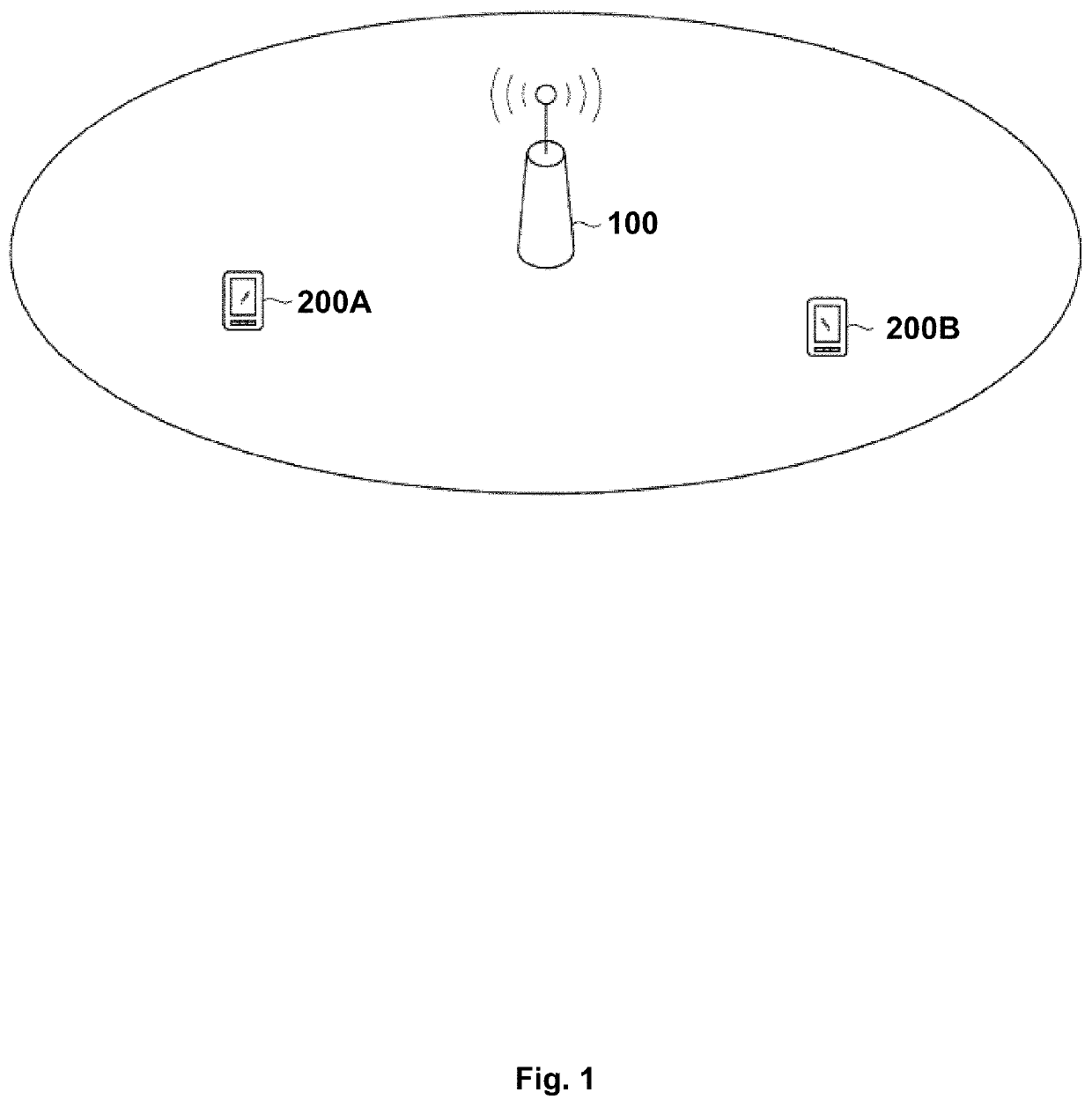
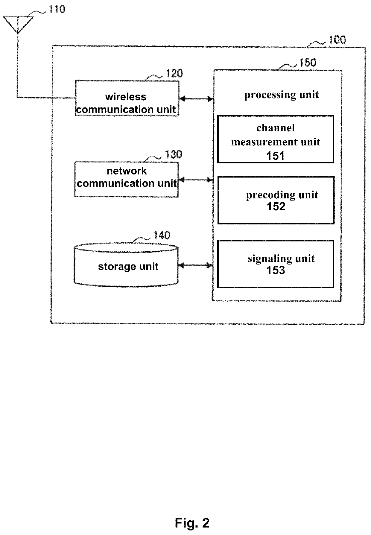
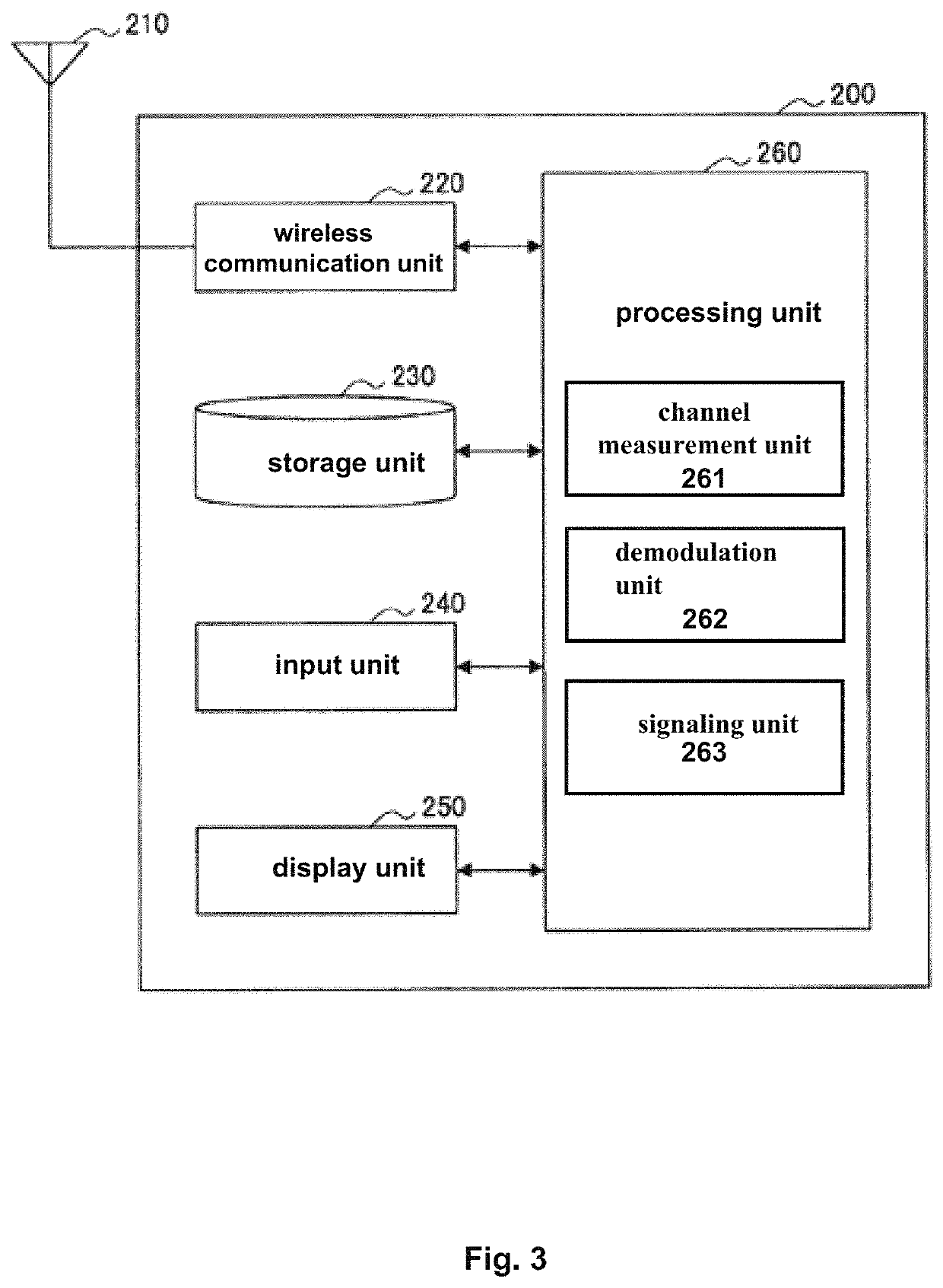
[0161]The technology of the present disclosure can be applied to various products. For example, the base station 100 and the terminal 200 may be implemented as various types of computing devices.

[0162]For example, the base station 100 may be implemented as any type of evolutionary node B (eNB), gNB or TRP (Transmit Receive Point), such as macro eNB / gNB and small eNB / gNB. A small eNB / gNB may be an eNB / gNB covering a cell smaller than a macro cell, such as pico eNB / gNB, micro eNB / gNB, and home (femto) eNB / gNB. Alternatively, the base station 100 may be implemented as any other types of base station, such as a NodeB and a base transceiver station (BTS). The base station 100 may include a main body (also known as a base station device) configured to control wireless communication; and one or more remote radio heads (RRH) arranged in a place different from the main body. In addition, the various types of terminals described below may operate as the base stations 10...

first application example

[0186]FIG. 18 is a block diagram illustrating an example of a schematic configuration of a smartphone 900 to which a technology of the present application may be applied. The smartphone 900 includes a processor 901, a memory 902, a storage 903, an external connection interface 904, a camera 906, a sensor 907, a microphone 908, an input device 909, a display device 910, a speaker 911, a radio communication interface 912, one or more antenna switches 915, one or more antennas 916, a bus 917, a battery 918, and an auxiliary controller 919.

[0187]The processor 901 may be, for example, a CPU or a system on a chip (SoC), and controls functions of an application layer and the other layers of the smartphone 900. The memory 902 includes RAM and ROM, and stores data and program that is executed by the processor 901. The storage 903 may include a storage medium such as a semiconductor memory and a hard disk. The external connection interface 904 is an interface for connecting an external device...

second application example

[0195]FIG. 19 is a block diagram illustrating an example of a schematic configuration of a car navigation device 920 to which an embodiment of the technology of the present application may be applied. The car navigation device 920 includes a processor 921, a memory 922, a global positioning system (GPS) module 924, a sensor 925, a data interface 926, a content player 927, a storage medium interface 928, an input device 929, a display device 930, a speaker 931, a radio communication interface 933, one or more antenna switches 936, one or more antennas 937, and a battery 938.

[0196]The processor 921 may be, for example, a CPU or a SoC, and controls a navigation function and other functions of the car navigation device 920. The memory 922 includes RAM and ROM, and stores data and program that is executed by the processor 921.

[0197]The GPS module 924 uses GPS signals received from a GPS satellite to measure a position, such as latitude, longitude, and altitude, of the car navigation devi...


PUM


Abstract

An electronic device operating on a base station side and includes a processing circuit configured to perform control to cause the electronic device to: estimate channel correlation in a first direction among a plurality of terminals communicating with the base station; and in response to that the estimated channel correlation in the first direction among the plurality of terminals satisfies a predetermined condition, transmit a first indication signal to indicate that a second measurement process is to be performed to determine channel information in a second direction after a first measurement process is to be performed to determine channel information in the first direction, and transmit, based on the channel information in the second direction, a second indication signal to indicate a precoding scheme for data to be transmitted from the base station to the plurality of terminals, the precoding scheme including linear precoding or non-linear precoding.

Description

CROSS-REFERENCE TO RELATED APPLICATIONS[0001]The present application is based on PCT filing PCT / CN2019 / 112207, filed Oct. 21, 2019, which claims the benefit of Chinese Patent Application No. 201811256542.X, filed on Oct. 26, 2018, entitled “Electronic Device, Communication Method and Medium”, each are hereby incorporated by reference in its entirety.TECHNICAL FIELD[0002]The present disclosure relates to electronic device, communication method and medium. More specifically, the present disclosure relates to electronic device, communication method and medium for hybrid precoding in Full-Dimension Multiple-Input Multiple-Output (FD-MIMO) systems.BACKGROUND[0003]Massive MIMO systems use precoding technology to achieve spatial multiplexing and improve spectrum efficiency. Known precoding techniques include Linear Precoding (LP) and Non-Linear Precoding (NLP). Traditional linear precoding includes Matched Filter (MF) precoding, Zero Forcing (ZF) precoding or Minimum Mean Square Error (MMS...

Claims


Application Information

Patent Timeline
Patent Type & Authority Patents(United States)
IPC IPC(8): H04B7/0452H04B7/0456H04B7/06
CPCH04B7/0452H04B7/0469H04B7/0478H04B7/0639H04B7/0456
Inventor LIU, WENDONGWANG, ZHAOCHENGCAO, JIANFEI
Owner SONY CORP
Learn More