Organic electroluminecent element and method of manufacturing same

a technology of electroluminecent elements and organic electroluminecent elements, which is applied in the direction of electroluminescent light sources, coatings, electric lighting sources, etc., can solve the problems of unsuitable practical use, inadequacies in storage stability and stability, etc., and achieve low luminescence starting potential and stable luminescence characteristics

Inactive Publication Date: 2001-06-14
MINOLTA CO LTD
View PDF0 Cites 42 Cited by
  • Summary
  • Abstract
  • Description
  • Claims
  • Application Information

AI Technical Summary

Benefits of technology

0015] In view of the aforesaid information, an object of the present invention is to provide an organic electroluminescent element having stable luminescence characteristics and low luminescence starting potential without black dot-like not luminescing areas in the luminescent surface, and method of manufacturing same.

Problems solved by technology

Although organic electroluminescent elements have high luminescence characteristics, they have inadequate storage stability and stability when luminescing and are as yet unsuitable for practical use.

Method used


Image

  • Organic electroluminecent element and method of manufacturing same
  • Organic electroluminecent element and method of manufacturing same
  • Organic electroluminecent element and method of manufacturing same

Examples


example 2

[0116] In this example, a manufacturing apparatus is used having chambers 100 and 101 of integrated construction, and chambers 102 and 103 uniformly constructed, said apparatus being identical to that used in example 1. A plasma washing mechanism is provided within the dry washing chamber 101.

[0117] The ITO membrane of a commercial glass substrate S provided with an ITO membrane (Geomatechn Co. Ltd.) was thoroughly cleaned with distilled water and acetone in ultrasound cleaning processes lasting 20 min, respectively, and the interior of chamber 100 was evacuated to a vacuum of less than 1.0.times.10-5 Torr via pump P.

[0118] Then, while maintaining the vacuum state, HI / Ar gas mixture was introduced to attain a vacuum of 2.0.times.10-2 Torr within chamber 100, and dry etching was performed for 3 min on substrate S via metal mask 110 at a voltage of 1 W / cm2. Next, etching was repeated at 20% of the previous output at a pressure of 0.1 Torr. The gas flow rate was 300 sccm.

[0119] There w...

example 3

[0125] Example 3 uses the manufacturing apparatus with chambers 100-103 of integrated construction, as shown in FIG. 7.

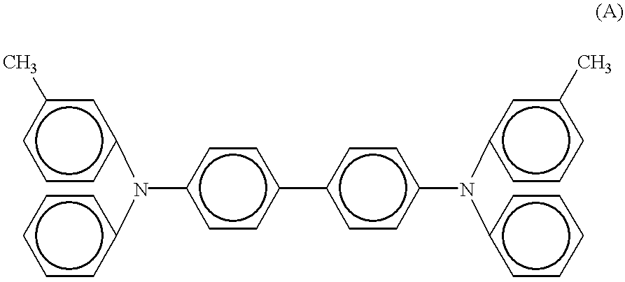
[0126] Just as in example 2, patterning and plasma washing of ITO substrate S was performed n chambers 100 and 101, and after dry washing via plasma process, the substrate S was moved into chamber 102 without exposure to air. Then, a triphenylamine dielectric represented by chemical structural formula A was vacuum deposited in a vacuum of 1.0.times.10-5 Torr to a layer thickness of 65 nm at a vacuum deposition speed of 5 A / sec to produce a hole injecting / transporting layer.

[0127] Then, while similarly maintaining the vacuum state within the chamber, tris(8-hydroxyquinoline) aluminum complex was vacuum deposited to a layer thickness of 65 nm at a rate of 6 A / sec to form a luminescing layer on substrate S.

[0128] The substrate S was then transported into chamber 103 without breaking the vacuum state, and a mixture of Mg and Ag was vacuum deposited together at a ratio o...

example 4

[0130] Example 4 uses a modification of the manufacturing apparatus shown in FIG. 9.

[0131] After glass substrate S was washed by ultrasonic cleaning using distilled water and acetone for 20 min, respectively, the pressure in the chamber was reduced to a vacuum of less than 1.0.times.10-5 Torr.

[0132] ITO alloy was deposited by spattering method at a deposition rate of 5 A / sec to form a layer 200 nm in thickness as a positive electrode. Then, plasma washing, organic compound layer, and negative electrode were performed in the same manner as described in example 3.

[0133] The organic electroluminescent element was manufactured via the aforesaid processes.


PUM


Abstract

The purpose of the invention is to provide an organic electroluminescent element having stable luminescent characteristics with a low luminescence starting voltage and without non-luminescing black spots in the luminescing surface. The invention relates to a method of manufacturing an organic electroluminescent element and an organic electroluminescent element produced by said method, said method of manufacturing an organic electroluminescent element comprising a process for forming a positive electrode substrate by dry etching a transparent electrode in a vacuum, a process for dry washing said positive electrode substrate in a continuous vacuum without exposure to air, a process for forming an organic layer incorporating an organic luminescing layer on said positive electrode substrate, and a process for forming a negative electrode on said organic layer.

Description

[0001] This application is based on Application No. HEI 9-113849 filed in Japan, the content of which is hereby incorporated by reference.[0002] 1. Field of the Invention[0003] The present invention relates to an organic electroluminescent element and method of manufacturing same.[0004] 2. Description of the Related Art[0005] Organic electroluminescent elements are elements constructed using organic compounds as light-emitting materials which emit light in accordance with electrical signals.[0006] Organic electroluminescent elements basically comprise an organic light-emitting layer interposed between a pair of opposing electrodes. Light emission is a phenomenon occurring when electrons are injected by one electrode and holes are injected by another electrode, so as to excite the light-emitting member within the light-emitting layer to a higher energy level, such that when the excited light-emitting member returns to its original lower energy state, the surplus energy is released as...

Claims


Application Information

Patent Timeline
Patent Type & Authority Applications(United States)
IPC IPC(8): H01L27/32H01L51/00H05B33/10H01L51/30H01L51/50H01L51/52H01L51/56H05B33/12H05B33/14H05B33/26
CPCH01L27/32H01L51/0059H01L51/0081H01L51/5206H01L51/5237H01L51/56H10K59/00H10K85/631H10K85/324H10K50/81H10K50/844H10K71/00
Inventor UEDA, HIDEAKIFURUKAWA, KEIICHITERASAKA, YOSHIHISA
Owner MINOLTA CO LTD
Why Eureka
Try Eureka