Method of manufacturing color filters and liquid crystal display device using these color filters

a technology of color filters and liquid crystal display devices, which is applied in the direction of photomechanical treatment originals, identification means, instruments, etc., can solve the problems of cumbersome process, limited product enhancement throughput, and difficult to uniformly diffuse dye into the dyed substra

Inactive Publication Date: 2001-07-12
HITACHI LTD +1
View PDF0 Cites 61 Cited by
  • Summary
  • Abstract
  • Description
  • Claims
  • Application Information

AI Technical Summary

Benefits of technology

[0021] Since this back exposure is performed using the black matrix as the exposure mask, an unhardened portion is present at the dyed substrate having the light hardening property which is coated on an upper portion of the black matrix and an upper portion of the dyed substrate layer of the pixel region which is disposed a given distance away from a substrate surface. By removing the unhardened portion in the subsequent developing process, a hardened dyed substrate layer having a given thickness can be obtained. At the same time, the surface shape and the layer thickness of the dyed substrate layer are made uniform so that the flatness can be ensured even when an overcoat layer having a thick thickness is not coated after dyeing.
[0023] To the contrary, in the present invention, since the flatness of the color filters per se is favorable, the overcoat layer which is coated on the upper layer of the color filters can be made thin so that the cell gap (the height of the gap defined between two substrates) of a liquid crystal display device can be made uniform. Further, this cell gap can be made small to a level which makes the tolerance of every lot ignored so that the display quality can be enhanced.
[0026] Due to such a provision, the mixed color which may be caused by the movement of the dye to the neighboring or adjacent neighboring pixels can be prevented. Further, since a sufficient amount of dye can be reserved in the ink reservoirs, by optimizing the supply amount of dye for each color, the dyeing with a given dyeing degree can be realized, whereby three colors are leveled with a given dyeing degree so that the uniform color tone can be obtained.
[0027] Further, by optimizing the layer thickness of the dyed substrate which anticipates the swelling caused by dyeing, the color filters whose height approximates the height of the partition walls of the black matrix can be formed whereby the film thickness of the overcoat layer can be made thin and the flattening becomes facilitated.
[0028] Further, in the present invention, pigment dispersed resists of given colors are respectively supplied to apertures formed by the black matrix so as to form color filters of respective colors. The same goes for when a so-called resist method is used. By applying the back exposure, the heights of the resists of respective colors can be approximated to the height of the black matrix so that the surface flatness of the color filter layer can be enhanced and the overcoat layer coated on the upper layer of the color filter layer can be made thin so that the uniform cell gap can be formed.
[0044] a fourth step in which the material other than the hardened portions is removed such that the height of the material formed for each aperture becomes lower than the height of the resin film at least at a central portion of the aperture.

Problems solved by technology

In the former method, since the resist in which a given pigment is dispersed is coated, exposed and developed for each color, that is, a so-called photolithography step is repeated to form the color filters, the process is cumbersome and there exists a limit in enhancing a throughput of products and further there may be a case that the color resist flows into or is scattered to neighboring or adjacent pixel regions thus giving rise to a mixed color.
Since the method which uses the sublimation dye is a method which performs a given dyeing by diffusing the sublimation dye in the dyed substrate layer (also called "reception layer") based on temperature, it is difficult to make the diffusion of the dye into the dyed substrate uniform by holding the temperature distribution uniform.
However, even with this ink jet method, there exists a possibility that the dyeing material such as dye, pigment or the like flows into or scatters to neighboring or adjacent pixel regions thus giving rise to a mixed color.
As mentioned above, in any one of the conventional techniques, the color resist or the dye flows into or scatters and is adhered to the neighboring or adjacent resin film or the dyed substrate and hence, a so-called "mixed color" (dyeing irregularity) is liable to occur.
However, with respect to the method which forms ink reservoirs in the black matrix, even after dyeing is completed, the black matrix is present as partition walls which are higher than respective pixel regions (color filter layers) and hence, the flatness of the surface of the color filter layers is deteriorated, whereby it is difficult to ensure the flatness of a protective film (overcoat layer), an electrode or an orientations film or the like which are formed as layers disposed above the color filter layers.
However, this becomes an obstacle in ensuring the flatness.
However, the degree that the dye permeates the dyed substrate (dyeing degree) is different depending on colors and this brings about the difference in concentration of the finished color filters.
As a result, it is difficult to level three colors to a given dyeing degree, that is, to make their color tone uniform so that the concentration of a specific color, for example, blue which is dyed with dye having a large molecular weight becomes high.
This is because that problems such as color irregularity (Chrominance) which occurs in the color filter manufacturing step using the conventional ink jet method which has been explained heretofore may occur in the steps for dropping a given amount of dyeing liquid for every pixels using the nozzle or the hollow needle.

Method used


Image

  • Method of manufacturing color filters and liquid crystal display device using these color filters
  • Method of manufacturing color filters and liquid crystal display device using these color filters
  • Method of manufacturing color filters and liquid crystal display device using these color filters

Examples


first embodiment

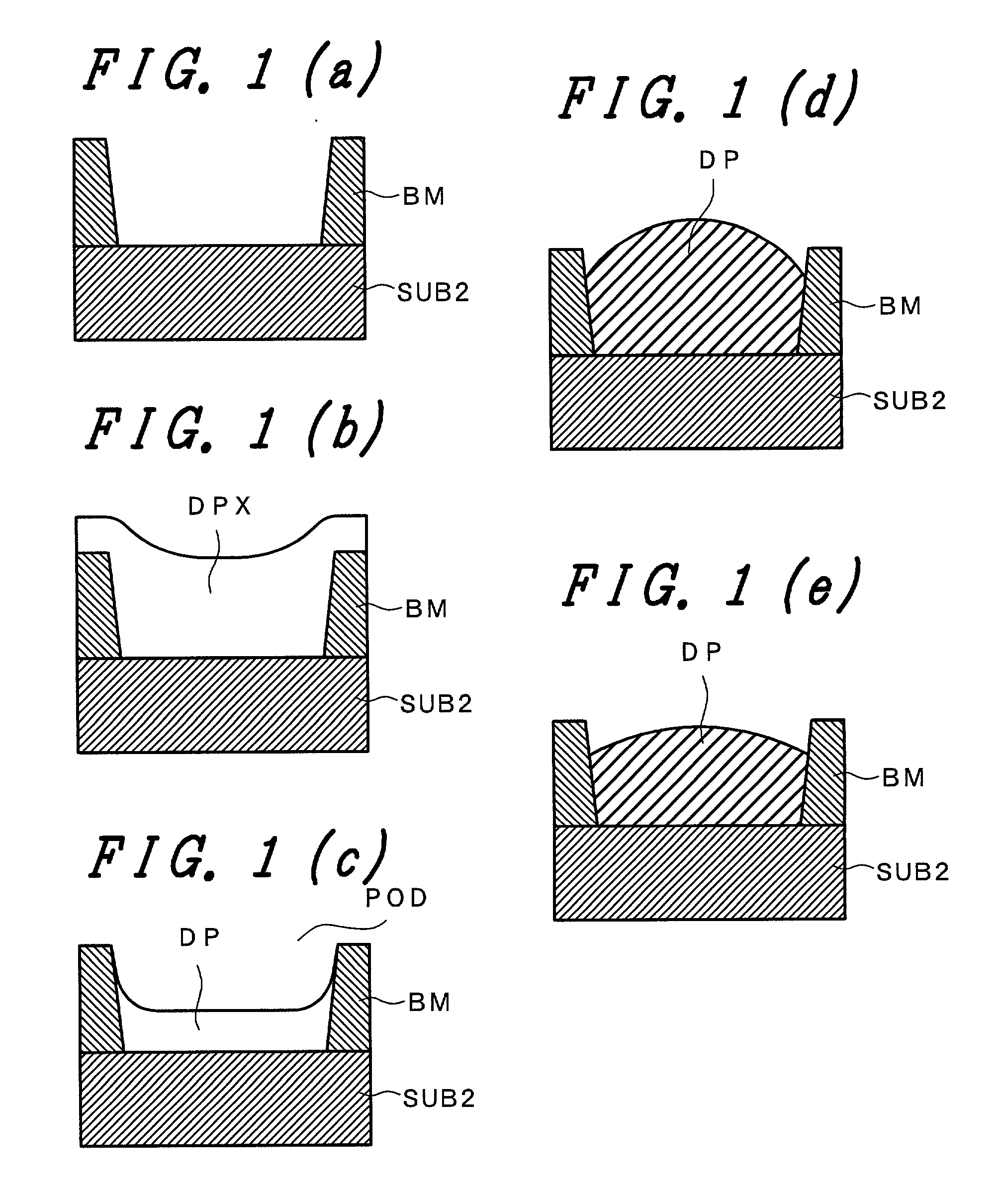
[0139] FIG. 10 is a schematic process view for explaining a color filter manufacturing method according to the present invention. In this embodiment, partition walls are formed of a black matrix made of a resin material for every pixels (pixel regions corresponding to color filters in respective colors). In aperture portions formed by these partition walls, indentations (ink reservoirs) are formed by dyed substrates to enable the supply of ink.

[0140] That is, on a first main surface of a glass substrate which constitutes a color filter substrate, a resist which disperses a black material such as graphite or metal oxide or the like in polymeric resin is coated. The resist is exposed through an exposure mask and developed to form a black matrix BM having given apertures (process-1, hereinafter abbreviated to P-1). In this embodiment, the film thickness of the black matrix BM is 1.4 .mu.m and its optical density (OD value) is 3.7. As the material of the black matrix BM, "BK series" pro...

second embodiment

[0173] FIG. 13 is a schematic process view for explaining a color filter manufacturing method of the present invention. In this embodiment, a negative-type photosensitive resin (color resist) which is preliminarily colored with pigment or dye is used. With the use of this photosensitive resin, a substrate which forms color filters corresponding to pixels in three colors by a photolithography process is obtained.

[0174] In this embodiment, a photosensitive color resist which disperses carbon as black pigment is coated on a first main surface of a color filter substrate SUB2 and then a patterning of the color resist is performed to form apertures of a black matrix BM (FIG. 13(a)).

[0175] Color resists REG (R), REG (G), REG (B) in respective colors are supplied into the apertures of the black matrix BM by an ink jet method. In supplying the color resists by the ink jet, it is difficult to control the color resists in respective colors at high accuracy for every apertures (pixels). Accord...

fifth embodiment

[0205] With the above-mentioned fourth and fifth embodiment, the color filters having given color tones can enhance the flatness of their upper surfaces so that the color filter substrate having a favorable surface flatness can be obtained with coating of the thin overcoat.


PUM

PropertyMeasurementUnit
thicknessaaaaaaaaaa
ODaaaaaaaaaa
thicknessaaaaaaaaaa

Abstract

After forming a black matrix which defines pixel regions on a substrate, dyed substrate layers of photo hardening property are formed. By irradiating ultraviolet rays to the dyed substrate layers from the back of the substrate and by developing, ink reservoirs which use the black matrix as partition walls are formed. The dyeing material such as the dye is supplied to these ink reservoirs by an ink jet system. Due to these partition walls, there is no possibility that the dyeing material scatters to the neighboring or adjacent pixel regions to cause the mixed color. Further, since the filters having a sufficient thickness can be formed in the ink reservoirs, the surface flatness of the color filters can be sufficiently ensured without coating the thick overcoat layer.

Description

[0001] 1. Field of the Invention[0002] The present invention relates to a liquid crystal display device, and more particularly to color filters for performing a full color display, a method for manufacturing the color filters, and a liquid crystal display device using the color filters.[0003] 2.Description of the Related Art[0004] A liquid crystal display device for a full color display includes switching elements such as electrodes and thin film transistors for selecting pixels on either one or both of two substrates and color filters in a plurality of colors (generally three colors) on the other substrate.[0005] As a method for manufacturing these color filters, a color resist method which forms color filters in three different colors by a photolithography technique which coats a resist made of high-molecular resin material in which various pigments are dispersed on a substrate (usually, a glass substrate) and thereafter performs exposure and development by way of a mask, and a dy...

Claims


Application Information

Patent Timeline
Patent Type & Authority Applications(United States)
IPC IPC(8): G02B5/20G02F1/1335B41J2/01G09F9/00G09F9/30
CPCG02B5/201G02F1/133512G02F1/133516G02F1/1335
Inventor MATSUYAMA, SHIGERUISHII, AKIRASHIMIZU, MIYO
Owner HITACHI LTD
Why Eureka
Try Eureka