
Reinforced cation exchange membrane and production process thereof

Inactive Publication Date: 2002-03-21
ASAHI KASEI KK
View PDF0 Cites 33 Cited by
  • Summary
  • Abstract
  • Description
  • Claims
  • Application Information

AI Technical Summary

Benefits of technology

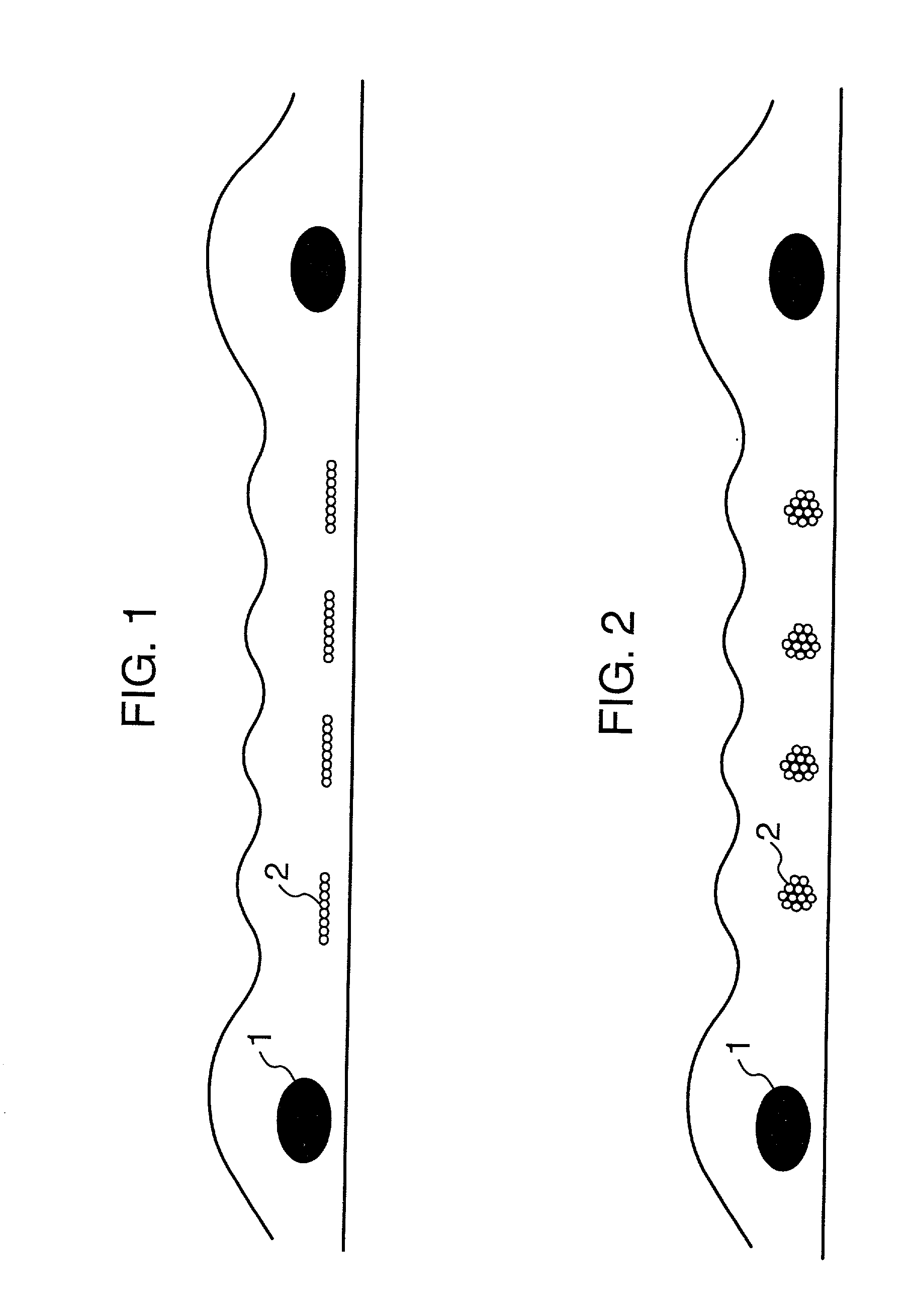
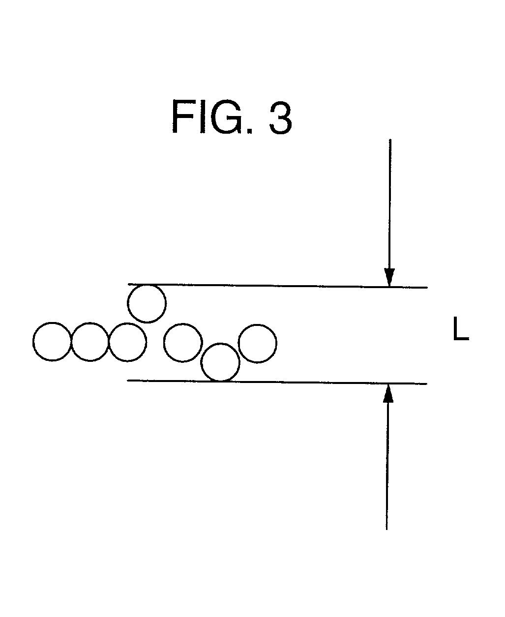
[0012] The present inventors have intensively studied to solve the problems as stated above, and as a result, they have found that, when the shape of a cross section of a channel after dissolution which is formed at a part where sacrificial threads have been dissolved, is made to be flat in a direction of a plane of the membrane, remarkable effect can be exhibited to solve the problems as stated above. Thus, the present invention has been accomplished.
[0026] The reinforced cloth according to the present invention can render the shape of a cross section of a channel after dissolution of sacrificial threads flat in a direction of a plane of the membrane, the channel after dissolution can be easily crushed at a portion of a cell flange of an electrolysis cell, the effect of preventing leak of an anode solution out of the cell flange can be exhibited. Thereby, the conventional applying of a silicone sealant or a fluorine type grease becomes unnecessary, and easy setting of the membrane to an electrolysis cell becomes possible.

Problems solved by technology

However, this perfluorocarbon type film has low tear strength, and does not endure a use for a long period by itself, and therefore tear strength thereof is improved usually by embedding a reinforcing material such as a reinforced cloth, etc. in the film.
However, a general reinforcing material is ionically non-permeable, and therefore when the reinforcing material is embedded in the film, a decrease of an effective electric current area and a raise of electric voltage for electrolysis accompanied thereby are caused on electrolysis.
Generally, in electrolysis of an alkali metal chloride under high electric current density, when the openness is made to be not higher than 70%, an effective electric current area of a membrane becomes short, and not only electric resistance of a membrane is increased, but also a transfer of impurities is locally increased, which causes a decrease of efficiency of electric current.
However, even by employing these methods as above, an openness of approximately 70% is at most, and when the openness of not lower than 70% is tried to attain, slippage of a stitch at a part of openings of a cloth is caused, which makes difficult a production of a cloth, and insertion thereof between films of a laminate.
However, employment of only the reinforcement threads is limitative to raising of openness (JP-A-3-217427).
However, there is such a problem that the tubular path is in connection with the whole of the cloth, namely with the whole of the membrane, on use in an electrolysis cell, a portion of the anode solution is apt to bleed out of a flange which fixes a membrane to the electrolysis cell, and thus a leak of the anode solution from the circumference of the membrane is caused.
This leak of the anode solution out of the vessel accelerates corrosion of an electrolysis cell and deterioration of a gasket, and, in the worst case, a short circuit is caused owing to a precipitation of a salt, and electrolysis sometimes is forced to be terminated.
Particularly, pressure on the surface of the flange in the longitudinal direction of the electrolysis cell sometimes is not uniform, and leak especially from the lower part of the electrolysis cell can be caused.
Therefore, when the electrolysis cell is equipped with a membrane, a channel after dissolution at the flange part is clogged, for instance, by applying a pasty silicone sealant or a fluorine type grease to the gasket.
However, depending upon the shape of an electrolysis cell, the coating takes much time and labor, and when thickness of the coating is not uniform, the sealant or the grease may protrude to an electric current conducting portion and an electrolysis cell, which are a problem.

Method used


Image

  • Reinforced cation exchange membrane and production process thereof
  • Reinforced cation exchange membrane and production process thereof
  • Reinforced cation exchange membrane and production process thereof

Examples


example 1

[0070] A taped yarn of a polytetrafluoroethylene (PTFE) of 150 denier was twisted at 900 times / m, and was made a filament-like to provide reinforcement threads. A yarn composed of 6 filaments of a polyethylene terephthalate (PET) of 30 denier and a ratio of shrinkage in a boiling water of 8% was twisted at 200 times / m to provide a warp of sacrificial threads. A yarn composed of 8 filaments of a polyethylene terephthalate (PET) of 35 denier and a ratio of shrinkage in a boiling water of 3% was twisted at 10 times / m to provide a weft thereof. By employing these yarns, a plain weave reinforced cloth was weaved so as to have reinforcement threads of PTFE at 16 / inch, and to have sacrificement threads of PET at 64 / inch, i.e. 4 times that of the former. The thickness of the cloth was 100 .mu.m. During the weaving of the cloth, the number of terminations owing to a weft was 55 times / 1000 m, and a fabricating property thereof was favorable.

[0071] After the weaving, the cloth was transferred ...

example 2

[0080] A plain weave reinforced cloth was weaved to obtain a composite membrane in the same way as in Example 1, except that sacrificial threads employed as weft were twisted at 30 times / m. As a result of observing a surface and a cross section of the membrane, a structure was observed wherein the shape of cross sections of almost all sacrificial threads of weft was flat in the direction of the plane of the cloth, and mono-filaments resided in a row without overlapping one another in the direction of thickness of the membrane. During the weaving of the cloth, the number of terminations owing to weft was 43 times / 1000 m, and the weaving property thereof was favorable.

[0081] By using this cloth, a composite membrane was prepared in the same method and conditions as in Example 1. As a result thereof, an openness of the membrane after hydrolysis was 81%. When the membrane was dried and a cross section thereof was observed, all of sacrificial threads were found to be dissolved, and the s...

example 3

[0083] A plain weave reinforced cloth was weaved to obtain a composite membrane in the same way as in Example 1, except that sacrificial threads employed as weft were twisted at 180 times / m. As a result of observing a surface and a cross section of the membrane, a structure was observed wherein the shape of cross sections of almost all sacrificial threads of weft was flat in the direction of the plane of the cloth but a portion of sacrificial threads exhibited a degree of flatness of 1.5. During the weaving of the cloth, the number of terminations owing to weft was 20 times / 1000 m, and the weaving property thereof was very favorable.

[0084] Next, the composite membrane was hydrolyzed in the same method and conditions as in Example 1. As a result thereof, an openness of the membrane was 81%. When the membrane was dried and a cross section thereof was observed, all of sacrificial threads were found to be dissolved, and the shape of channel after dissolution was flat as same as that of ...


PUM

PropertyMeasurementUnit
Fractionaaaaaaaaaa
Fractionaaaaaaaaaa
Linear densityaaaaaaaaaa

Abstract

A cation exchange membrane wherein a plain weave reinforced cloth is embedded in a fluorinated polymer having a sulfonic acid group and / or a carboxylic acid group, characterized by possessing therein a tubular path which is formed in a direction of a warp and a weft of the plain weave reinforced cloth and has a cross section flat to a direction of thickness of the membrane.

Description

[0001] (1) Field of the Invention[0002] The present invention relates to an ion exchange membrane for electrolysis, more specifically to an ion exchange membrane reinforced with a cloth comprising reinforcement threads and sacrificial threads which are used for electrolysis of an alkali metal chloride aqueous solution. Particularly, it relates to a fluorine-containing type ion exchange membrane having an excellent electrochemical property and an excellent mechanical property which prevents an anode solution from leaking out of a system through a channel after dissolution of sacrificial threads in the membrane.[0003] (2) Description of the Related Art[0004] It is already known in this field that as a solid electrolyte used for a membrane for separation in electrolysis of an alkali metal chloride, laminated membranes of at least two layers containing a perfluorocarbon carboxylic acid layer and a perfluorocarbon sulfonic acid layer are effective. High current efficiency, low electric r...

Claims


Application Information

Patent Timeline
IPC IPC(8): B32B5/02B01J47/12C25B13/08D03D1/00D03D15/00D06M11/00D06M11/38
CPCD03D15/00D03D15/08D10B2201/24D10B2321/042D10B2331/04D10B2401/061D10B2401/063D10B2401/10Y10T428/249975Y10T428/249953Y10T442/2508Y10T442/3146Y10T442/3106D03D15/56D03D15/41D03D15/283
Inventor SAKUMA, YUICHIHIRANO, TOSHINORI
Owner ASAHI KASEI KK
Learn More