Sputtering method and apparatus for depositing a coating onto substrate
- Summary
- Abstract
- Description
- Claims
- Application Information
AI Technical Summary
Benefits of technology
Problems solved by technology
Method used
Image
Examples
example 1
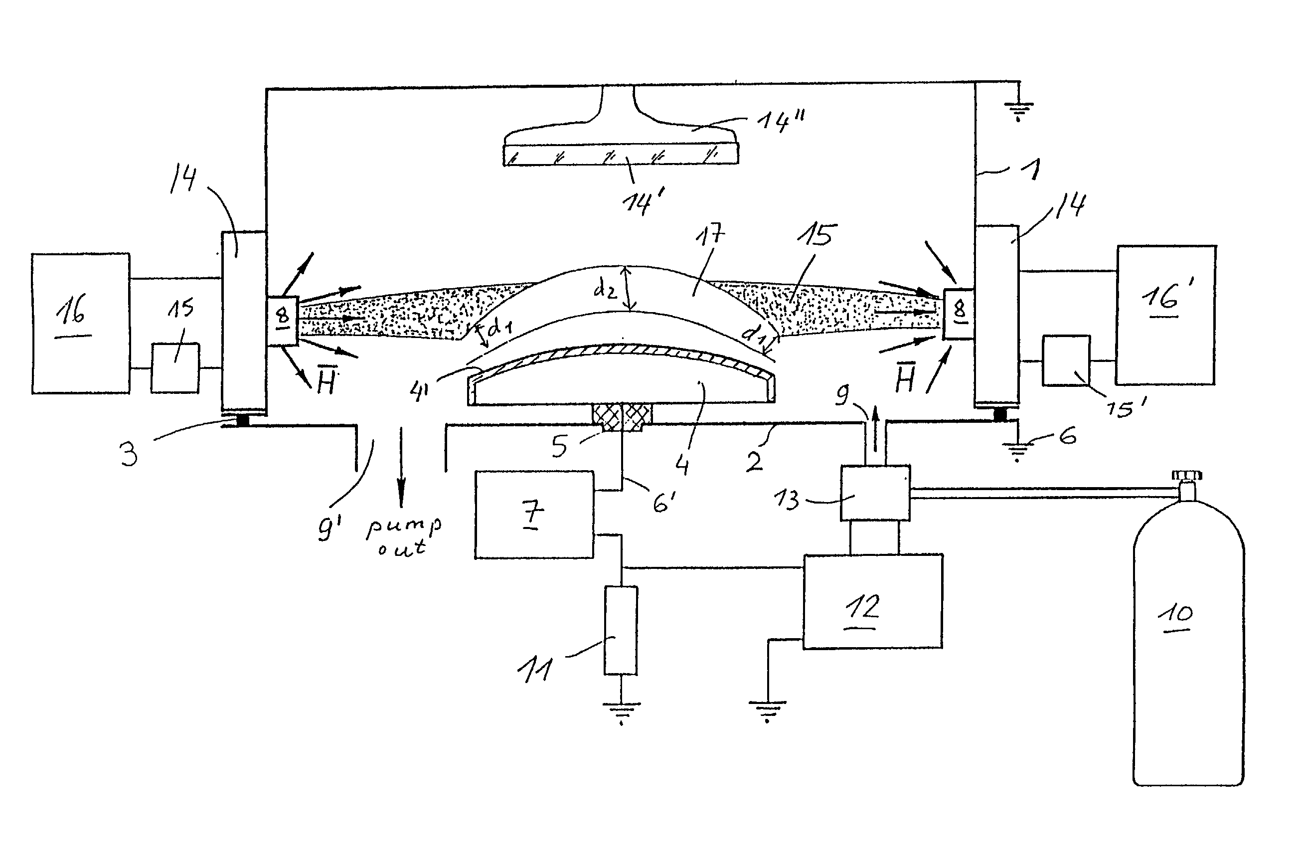
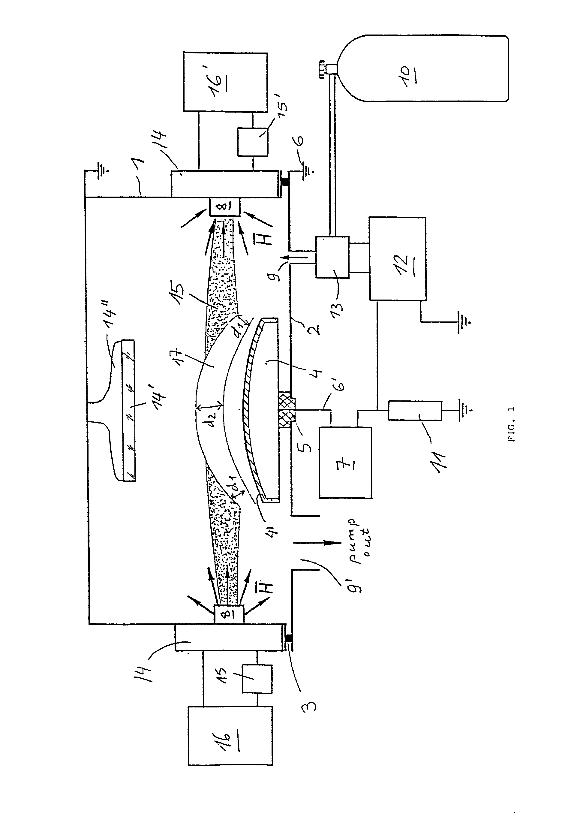
[0104] The substrate 14' is mounted on the substrate holding means so as to face the target surface 4' and to be spaced therefrom by a distance 5-20 cm.
[0105] The chamber 1 is sealed; its interior is evacuated up to pressure 0.001-0.004 Pa.
[0106] The current supply 16 is initiated and parameters of magnetic field are adjusted by means of a control means 15, so as to create a magnetic strength gradient, sufficient for localization of plasma within a region, separated by a distance of 3-15 cm from the substrate 14.
[0107] The power supply 7 is initiated and a potential of 2-5 kV, negative with respect to grounded chamber 1 is supplied to the cathode pole structure 4.
[0108] By means of current sensor 11 the value of discharge current is adjusted and the stream of reactive gas mixture is fed into the chamber from the source 10, up to building working pressure, sufficient for maintaining of self-sustained glow discharge. Particular parameters suitable for deposition of Al.sub.2O.sub.3 coa...
example 2
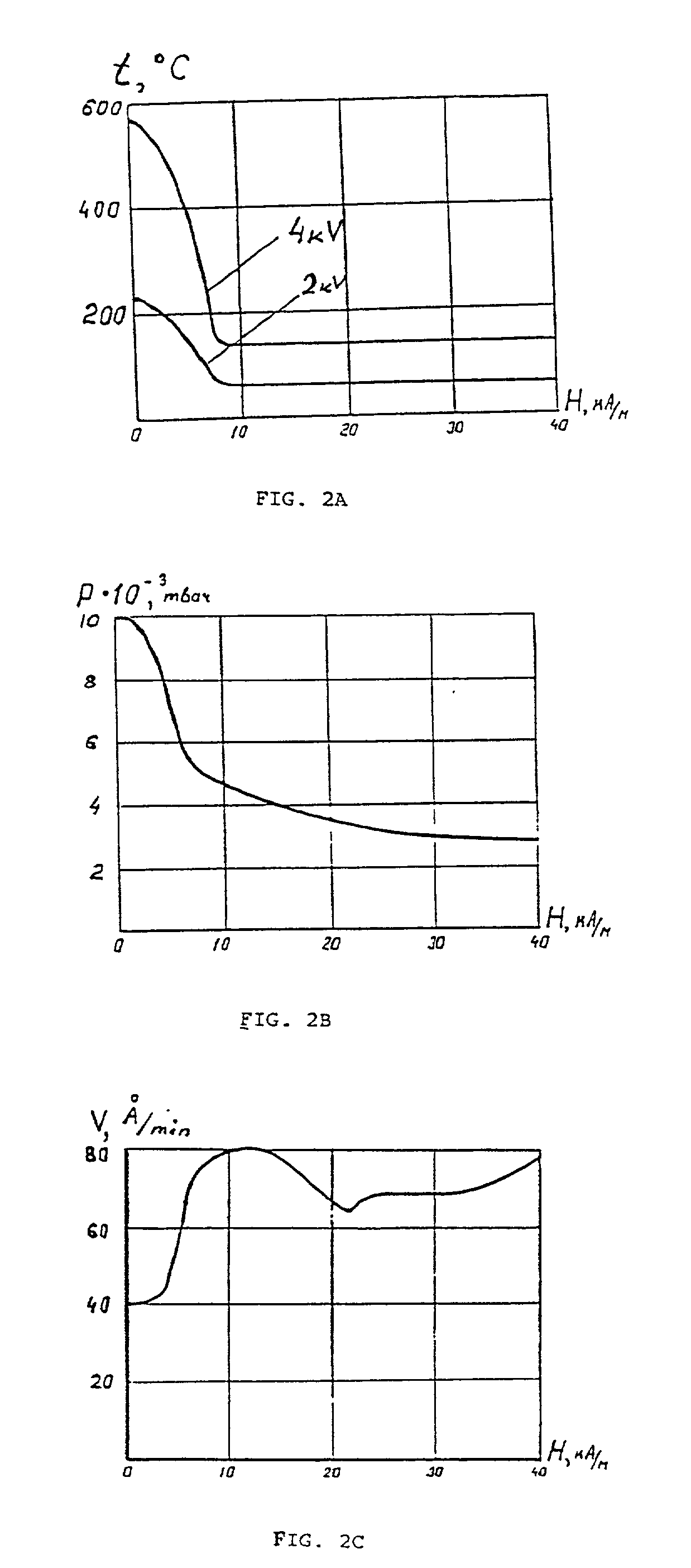
[0116] In this example, it will be explained how substrate temperature, reactive gas pressure and deposition rate depend on magnetic strength in the vicinity of the target, established during sputtering and configured in accordance with the present invention. Sputtering conditions:
[0117] Water cooled cathode, made of stainless steel, provided with Al target, having
[0118] square configuration 100.times.300 mm.
[0119] Anode-cathode distance: 60 mm
[0120] Reactive gas: mixture of 80% argon with 20% oxygen
[0121] Supplied voltage: 4 kV or 2 kV
[0122] Supplied power: 1.2 kW and 0.6 kW respectively
[0123] Resulting coating: Alumina This positive effect might be attributed to favorable conditions associated with formation of the coating, seeing that reduction of deposition temperature directly and indirectly influences coating properties and adhesion of the coating to the substrate.
[0124] In FIG. 3(A), it is shown that the refraction index (n) of the Ta.sub.2O.sub.5 coating, deposited in accord...
example 3
[0128] This example demonstrates that the coatings deposited by the present sputtering deposition method possess good chemical resistance. The following conditions were employed:
[0129] Water cooled cathode with diameter 60 mm.
[0130] Supplied negative voltage: 2 kV
[0131] Discharge current: 300 mA
[0132] Reactive gas mixture: 80% Oxygen, 20% Argon
[0133] Working pressure: 0.004 mbar
[0134] Target material: Si
[0135] Substrate material: Kronglass
[0136] Magnetic field strength in vicinity of anode: 40 kA / m
[0137] Magnetic field strength in vicinity of target surface: 12 kA / m
[0138] Resulting coating: SiO.sub.2
[0139] To evaluate the chemical resistance, coated and uncoated glass samples were exposed to 80% solution of sulfuric acid at 80.degree. C. for 8 hours and concentration of certain elements was measured before and after exposure within the sample. The uncoated samples were made of Kronglass. A 0.4 .mu.km-thick SiO.sub.2 coating was deposited on both sides of the sample.
[0140] Si, Na and...
PUM
| Property | Measurement | Unit |
|---|---|---|
| Length | aaaaa | aaaaa |
| Angle | aaaaa | aaaaa |
| Angle | aaaaa | aaaaa |
Abstract
Description
Claims
Application Information
 - R&D
- Intellectual Property
- Life Sciences
- Materials
- Tech Scout
- Unparalleled Data Quality
- Higher Quality Content
- 60% Fewer Hallucinations
Browse by: Latest US Patents, China's latest patents, Technical Efficacy Thesaurus, Application Domain, Technology Topic, Popular Technical Reports.
© 2025 PatSnap. All rights reserved.Legal|Privacy policy|Modern Slavery Act Transparency Statement|Sitemap|About US| Contact US: help@patsnap.com


