
Method for preparing silicon single crystal and silicon single crystal

Inactive Publication Date: 2002-10-31
SHIN-ETSU HANDOTAI CO LTD
View PDF0 Cites 24 Cited by
  • Summary
  • Abstract
  • Description
  • Claims
  • Application Information

AI Technical Summary

Benefits of technology

[0035] Description will be given of experiments performed for confirmation of the effect of the invention and results thereof.
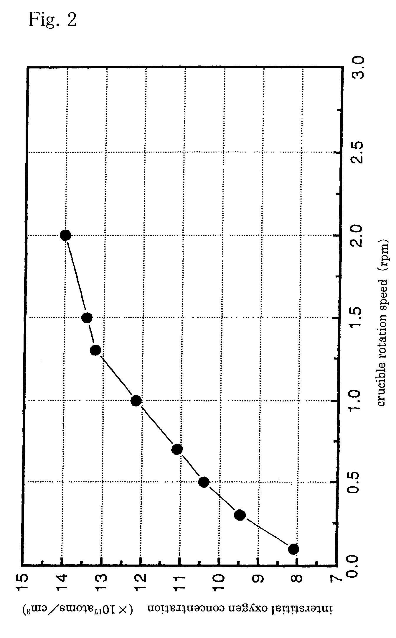
[0036] First of all, an experiment was performed that confirms an influence of a rotation speed of a crucible on an interstitial oxygen concentration (this is a preliminary experiment for showing a comparative example). At first, a raw material polycrystalline silicon 150 kg was put into a quartz crucible of 24 inches in diameter, the polycrystalline silicon was melted into a silicon melt and the melt was applied with a horizontal magnetic field of 4000 G. Ar gas as an inert gas was caused to flow in the growth furnace, a seed crystal was dipped into the silicon melt and thereafter, seed squeezing was performed, followed by growth of a silicon single crystal of 200 mm in diameter. Growth conditions were as follows: an Ar gas flow rate was 100 l / min and a pressure in the furnace was 100 mbar, both being fixed values and on the other hand, crucible rotation speeds ranging from 0.1 to 2.0 rpm were selected to set one value for growth of each of 8 kinds of silicon single crystal ingots. After growth of each of the silicon single crystal ingots, a silicon wafer of 2 mm thick was cut out from the position of the constant diameter part in each of obtained silicon single crystal ingots and the silicon wafers were polished on both sides thereof to measure an interstitial oxygen concentration according to F-121 of ASTM(1979) using a Fourier transform infrared: FTIR spectrometer. Results of the measurement are shown in FIG. 2. It is found from the results that as a rotation speed of a crucible increases, an interstitial oxygen concentration in each silicon single crystal increases. This means that by adjusting a crucible rotation speed in company with progress in growth of a silicon single crystal (that is, with increase in growth length), an interstitial oxygen concentration can be controlled.

Problems solved by technology

Therefore, characteristically, not only does a silicon wafer from such a single crystal come to have a large resistance force against various thermal strains received when semiconductor elements are fabricated thereon, but dislocations such as slippage are also difficult to be produced therein (see K. Sumino: Semiconductor Silicon 1981, Electrochem. Soc., Penington 1981 p.
However, on the other hand, as interstitial oxygen existing in a wafer increases, a forming amount of BMDs also increase and with the forming amount in excess, especially, in a wafer surface layer which is an element forming region, the BMDs are a cause for a leakage failure at element junction interfaces, which in turn invites deterioration in element characteristics, resulting in loss of an essential function of a semiconductor integrated circuit by chance.
Therefore, it is very important when semiconductor elements are fabricated in the surface layer of a wafer to keep an interstitial oxygen concentration in a CZ method silicon single crystal at a proper value, which produces a problem of how to control an interstitial oxygen concentration in a crystal at proper value in order to take care of a high density and high degree of integration of a semiconductor device, such that the control of an interstitial oxygen concentration have further become an important factor in maintaining a product quality of an integrated circuit.
As a result, oxygen dissolved from the crucible wall also decreases, in turn an oxygen concentration in the latter half of a grown crystal decreases to a value equal to or less than a desired value, and thereby, there arises a chance to be unable to ensure a necessary quality.
In this method, however, it has been said to be hard to achieve a high precision control of an interstitial oxygen concentration adapting to growth of a single crystal since, in a quartz crucible of as large a size as a diameter in excess of 200 mm, there exists a distance between a crucible wall supplying oxygen and a crystal growth interface, which in turn causes a delay in time for a melt to reach the crystal growth interface.
As a result, in a case where a large size crystal equal to or more than, especially, 200 mm in diameter is pulled, there has been an inevitable limitation on control to suppress variations in interstitial oxygen concentration due to the above inconvenience.
In one aspect of this method, however, somewhat troublesome faults have been encountered in setting of and adjustment for growing conditions of a single crystal since an oxygen concentration is excessively low by chance depending on growth conditions for a single crystal when a BMD density is desired at a necessary and sufficient level in a wafer, therefore, a special technique is required to be performed for achieving a high oxygen concentration on a specific target quality of a crystal and a growth state of the crystal.
In the MCZ method, however, by growing a silicon single crystal under application of a magnetic field to a silicon melt, a turbulent in the melt produced by thermal convection in the melt and rotation of a crucible can be efficiently suppressed, so an amount of oxygen supplied to a region in the vicinity of a crystal growth interface is caused low, with the result that a single crystal of a low oxygen concentration can be grown.
According to a prior art MCZ method, however, in use of a large size quarts crucible for growth of a single crystal as large a diameter as to exceed 200 mm, as described above, convection in a silicon melt is extremely suppressed by a magnetic field and thereby, more of a delay in time arises for a melt portion on a crucible wall surface to reach a growth interface, which in turn results in more of difficulty in terms of high precision control of an interstitial oxygen concentration adapting to growth of a crystal.
Note that, in a MCZ method, although a proposal is made on a method adjusting an oxygen amount supplied into a silicon melt from a crucible wall in which as an pulling amount of a single crystal ingot increases, a magnetic field applied to the silicon melt is reduced in strength, this has not been able to be a decisive solution as great as to be dramatic improvement of suppression of variations in interstitial oxygen concentration in pulling a single crystal of equal to or more than 200 mm in diameter either.
Especially, in a large diameter single crystal of 200 mm or more (for example, 8 inches), 250 mm or more (for example, 10 inches) or 300 mm or more (for example, 12 inches), it was traditionally very difficult to restrict variations in interstitial oxygen concentration to a sufficiently low level even by adopting an MCZ method.
With no relation to an amount of a melt in a crucible, an effect of removing an oxide evaporating from the surface of the melt becomes low with a flow rate of the inert gas flowing in the furnace equal to or less than 40 l / min and thereby, a case arise by chance where it is hard to properly control an oxygen concentration in the melt.
Furthermore, an effect of removing an oxide evaporating off away from the melt becomes low: therefore, not only does the upper end of a quarts crucible and an oxide attach onto portions which have low temperature in the growth furnace to contaminate the inner structure of the growth furnace, but also the attachment has a chance to fall onto the surface of the melt to disturb cystallization of silicon.
On the other hand, the inert gas flow rate more than necessary is also problematic.
When an amount of the inert gas is in excess, an amount of oxygen to be removed from the melt surface increases and an amount of oxygen supplied from the crucible increases in a corresponding manner, whereby deterioration of a quartz crucible is accelerated, resulting in difficulty in operation for a long time.
Furthermore, when an amount of the inert gas flowing over the melt surface increases, ripples arise on the melt surface, by which there arises a fear that the ripples produce an inconvenience such as to create dislocations in a single crystal in growth and further, which brings a disadvantage in an aspect of manufacture cost because of increase in consumption of the inert gas.
Under a pressure in the growth furnace of 40 mbar or less, an amount of an oxide such as SiO evaporating off away from the surface of a melt increases to a level in excess of a necessary value and an amount of supply of oxygen from a quartz crucible wall increases to thereby deteriorate a durability of the crucible; therefore, there arise a case where single crystal growth over a long time becomes difficult.
On the other hand, in a case where operation is performed under a condition in excess of 300 mbar, while an amount of oxide evaporating from the melt can be suppressed, a pressure in the growth furnace becomes excessively high, whereby SiO attaches on a furnace wall, a hot zone (a structure in the furnace) and others to disable visual observation in the furnace or crystal growth suffers falling-off of the attached SiO onto the melt resulting in disturbance of growth of a crystal by chance, which is not preferable from the viewpoint of actual operation.
Especially, since the center of the magnetic field is located on a crystal growth axis in the melt, a suppressing effect on convection in the vicinity of a crystal growth interface is large and it takes a time from when a rotation speed of a crucible is altered till an influence of the change in rotation speed is exerted on an oxygen concentration in the melt in the vicinity of a crystal growth interface, having resulted in a problem in regard to precise control of an amount of oxygen incorporated into a crystal.

Method used


Image

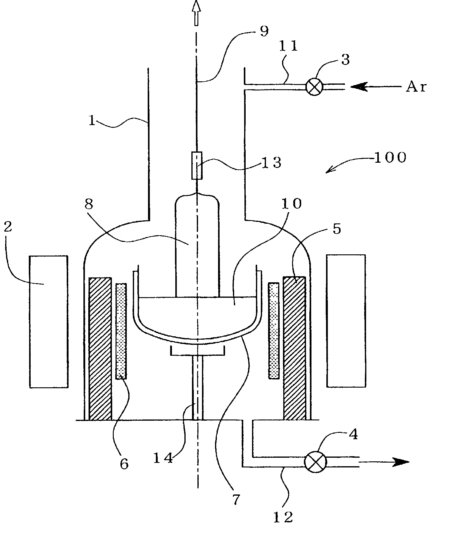
  • Method for preparing silicon single crystal and silicon single crystal
  • Method for preparing silicon single crystal and silicon single crystal
  • Method for preparing silicon single crystal and silicon single crystal

Examples


example 1

[0037] Then, attention was focused on an amount of evaporation of oxygen from the surface of a silicon melt and investigation was performed about an influence of an argon gas flow rate in the growth furnace, which is thought will affect the amount of evaporation of oxygen, on an interstitial oxygen concentration in a silicon single crystal. Growth conditions for growth of silicon single crystals were almost the same as those for the comparative example, wherein a fixed crucible rotation speed was 0.5 rpm and a fixed pressure in the growth furnace was 100 mbar; and an argon gas flow rate was altered in various ways in the range of from 25 to 300 l / min. An interstitial oxygen concentration of each of silicon single crystal ingots obtained on the respective growth conditions was measured in a similar method to that of the comparative example. Results are shown in FIG. 3. It is found from the results that as an argon gas flow rate increases, an interstitial oxygen concentration in a sil...

example 2

[0038] Furthermore, since it was estimated that a pressure in the growth furnace was related with an amount of evaporation of oxygen from the surface of a silicon melt, investigation was performed about an influence of a pressure in the growth furnace on an interstitial oxygen concentration in a silicon single crystal obtained. Growth conditions for growth of silicon single crystals were almost the same as those for the comparative example, wherein a fixed crucible rotation speed was 0.5 rpm and a fixed argon gas flow rate was 100 l / min; and a pressure in the growth furnace was altered in various ways in the range of from 70 to 300 mbar. An interstitial oxygen concentration of each of silicon single crystal ingots obtained in the respective growth conditions was measured in a similar method as that of the comparative example. Results are shown in FIG. 4. It is found from the results that as a pressure in the growth furnace increases, an interstitial oxygen concentration in a silicon...

example 3

[0039] Pulling of a silicon single crystal was performed while a crucible rotation speed (the comparative example) or an argon gas flow rate and a pressure in the growth furnace are continuously altered in company with progress in growth length of the silicon single crystal and investigation was performed in an experiment about whether or not control was performed so as to attain an interstitial oxygen concentration along the growth axis direction at a constant value. As described above, a crucible rotation speed is thought as a factor giving an influence on thermal convection in a silicon melt in the crucible and an argon gas flow rate and a pressure in the growth furnace are thought as factors giving influences on evaporation of oxygen atoms from the surface of a silicon melt.

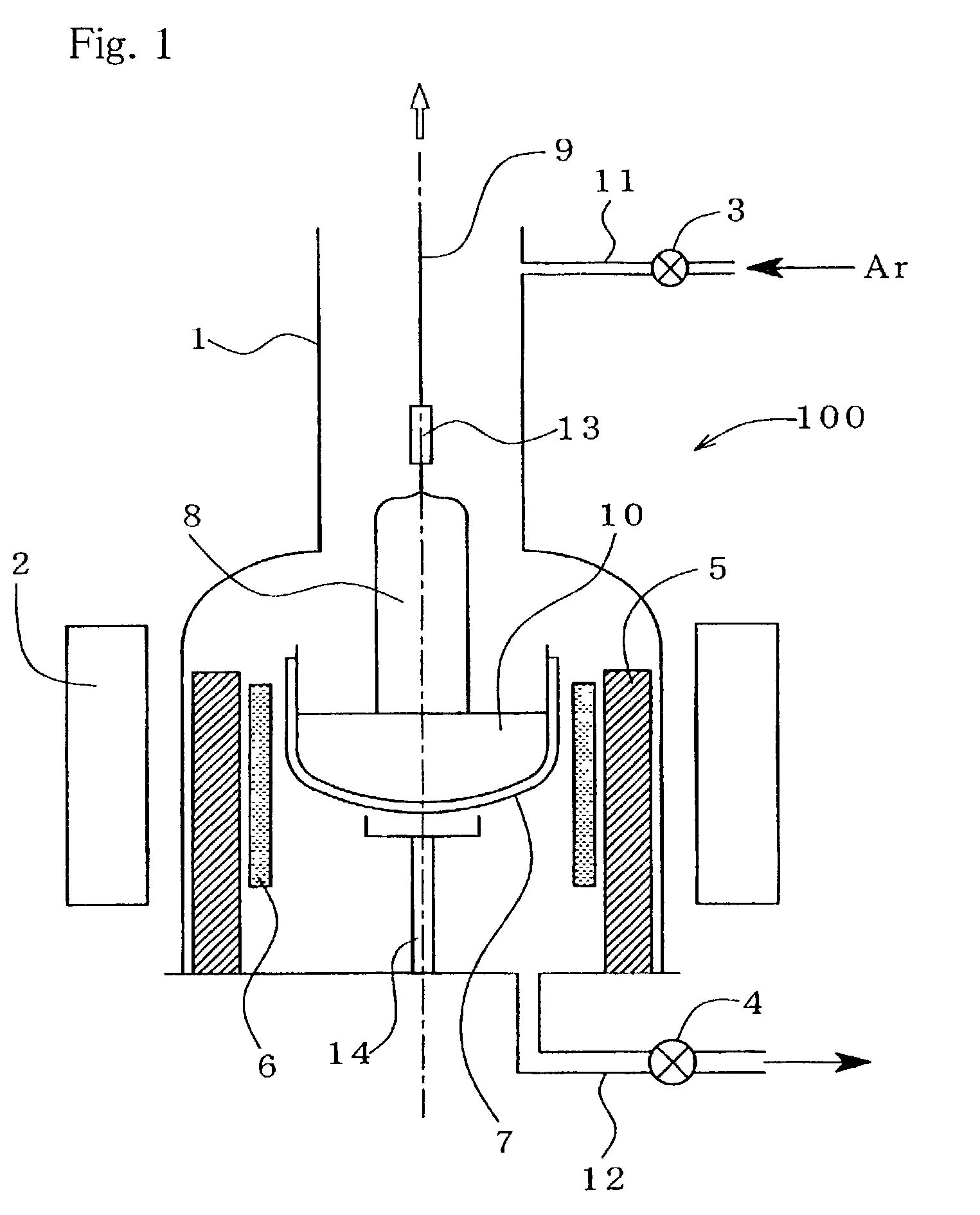
[0040] Pulling of the silicon crystal 8 was performed using the apparatus shown in FIG. 1, as an example, controlling both of an argon gas flow rate and a pressure in the growth furnace 1. An argon gas flow r...


PUM


Abstract

In a method manufacturing a silicon single crystal 8 according to an MCZ method, a flow rate of an inert gas flowing in a growth furnace 1 during growth of the silicon single crystal 8 and / or a pressure in the growth furnace 1 is altered according to a pulling amount of the silicon single crystal 8 to adjust an interstitial oxygen concentration therein. By altering a flow rate of an inert gas flowing in the growth furnace or a pressure therein, an amount of oxygen evaporating as an oxide from a surface of a silicon melt 10 in the vicinity of a crystal growth interface can be easily adjusted, and thereby, an oxygen amount included in the silicon melt 10 can be controlled with ease.

Description

[0001] This invention relates to a manufacturing method for a silicon single crystal, using a CZ method (a Czochralski Method) pulling the silicon single crystal from a silicon metal contained in a crucible. More particularly, the invention relates to a method obtaining a high quality silicon single crystal by controlling an interstitial oxygen concentration in the silicon single crystal with a high precision and a silicon single crystal that can be realized by the method for the first time.DESCRIPTION OF THE BACKGROUND ART[0002] In order to produce a silicon single crystal wafer used in fabrication of semiconductor devices, there has been widely used a silicon single crystal manufactured by a Czochralski method (hereinafter also referred to as a CZ method or a pulling method), which is advantageous in growing a large size crystal. A manufacturing method according to the Czochralski method is, as is well known to the general public, such that a seed crystal is dipped into a silicon ...

Claims


Application Information

Patent Timeline
IPC IPC(8): C30B15/00C30B15/30
CPCC30B15/305Y10S117/917C30B29/06C30B15/00
Inventor FUSEGAWA, IZUMIHOSHI, RYOJIINOKOSHI, KOUICHIOHTA, TOMOHIKO
Owner SHIN-ETSU HANDOTAI CO LTD
Learn More